
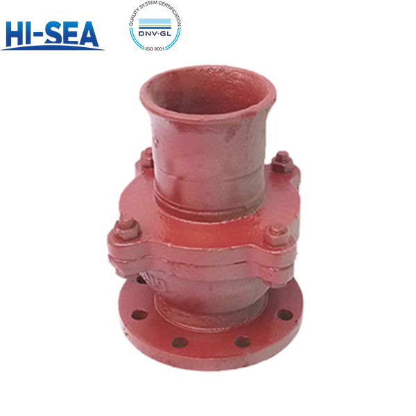
Overview
Flange Suction Check Valve (Foot Valve) is an automatic non‑return valve specially designed for marine pump suction piping. It permits unidirectional flow and closes automatically to stop backflow, with no manual isolation function. It adopts CB/T3478‑92 standard, PN10, covering DN32‑DN250. Suitable for fresh water, seawater and fuel oil up to 80℃. It has cast iron body and cover, rubber soft sealing seat, stainless steel built‑in strainer screen, and PTFE or rubber gasket as specified. Install vertically with the strainer end submerged into liquid, flow direction from strainer side into the valve. Each valve is pressure‑tested per GB/T 600. Confirm nominal diameter, flange type and gasket material before ordering; it shall not be installed horizontally or tilted, otherwise reliable closing cannot be guaranteed.
Basic Sructure of Flange Suction Check Valve Type R/RS
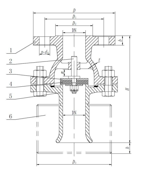
Index Description 1 — Valve body 2 — Valve stem 3 — Valve disc 4 — Sealing ring 5 — Suction inlet 6 — Strainer (optional, specify separately if required)
Basic parameters(CB/T3478-1992 )
| Type | Nominal Pressure PN | Nominal Size DN | Applicable Medium | Working Temperature | Flange Standard | Installation Method |
|---|---|---|---|---|---|---|
| R, RS, Y, YS | 1 | 32~250 | Oil, seawater, fresh water | ≤80℃ | CB/T 3478‑92 | Vertical installation, strainer end submerged in liquid |
Working Principle
This lift-type suction check valve (foot valve) is fitted at the pump suction end. When the pump starts, fluid lifts the valve disc to open. After pump shutdown, fluid weight and back pressure close the disc to prevent backflow and keep the pump primed. The optional strainer filters impurities.
Basic dimensions(CB/T3478-1992 )
Type R
| DN | Structure dimension | flange | bolt | |||||||
| H | h | D3 | D | D1 | D2 | d0 | b | n | Th. | |
| 32 | 150 | 15 | 85 | 115 | 83 | 64 | 15 | 13 | 6 | M14 |
| 40 | 170 | 17 | 95 | 125 | 93 | 74 | ||||
| 50 | 194 | 21 | 120 | 135 | 103 | 84 | ||||
| 65 | 210 | 26 | 150 | 155 | 123 | 104 | ||||
| 80 | 230 | 30 | 180 | 170 | 138 | 118 | 14 | 8 | ||
| 100 | 269 | 39 | 230 | 190 | 158 | 138 | 15 | |||
| 125 | 290 | 47 | 280 | 215 | 183 | 164 | 10 | |||
| 150 | 335 | 57 | 335 | 240 | 208 | 190 | 12 | |||
| 200 | 395 | 73 | 440 | 295 | 264 | 247 | ||||
| 250 | 508 | 91 | 545 | 365 | 327 | 306 | 17 | 18 | 14 | M16 |
Type RS
| DN | Structure dimension | flange | bolt | |||||||
| H | h | D3 | D | D1 | D2 | d0 | b | n | Th. | |
| 32 | 150 | 15 | 85 | 120 | 90 | 70 | 14 | 16 | 4 | M12 |
| 40 | 170 | 17 | 95 | 130 | 100 | 80 | ||||
| 50 | 194 | 21 | 120 | 140 | 110 | 90 | ||||
| 65 | 210 | 26 | 150 | 160 | 130 | 110 | ||||
| 80 | 230 | 30 | 180 | 190 | 150 | 128 | 18 | 18 | M16 | |
| 100 | 269 | 39 | 230 | 210 | 170 | 148 | ||||
| 125 | 290 | 47 | 280 | 240 | 200 | 178 | 20 | 8 | ||
| 150 | 335 | 57 | 335 | 265 | 225 | 202 | ||||
| 200 | 395 | 73 | 440 | 320 | 280 | 258 | 22 | |||
| 250 | 508 | 91 | 545 | 375 | 335 | 312 | 24 | 12 | ||
Materials of principal parts(CB/T3478-1992 )
| Part Name | Code | Material Name | Grade | Standard | |
|---|---|---|---|---|---|
| Valve Body, Suction Inlet | T | Cast Iron | HT200 | GB/T 9439—2023 | |
| H | Cast Bronze | ZCuZn16Si4 | GB/T 1176—2013 | ||
| N | Stainless Steel | CF3M | GB/T 12230—2023 | ||
| Type R, RS | Sealing Ring | — | Nitrile Rubber | NBR | HG/T 2811—1996 |
| Type R, RS Type Y, YS |
Valve Stem | — | Silicon Brass | HSi80-3 | GB/T 4423—2020 |
| — | Stainless Steel | 06Cr19Ni10 | GB/T 1220—2007 | ||
| Valve Disc | — | Cast Bronze | ZCuZn16Si4 | GB/T 1176—2013 | |
| — | Stainless Steel | CF3M | GB/T 12230—2023 | ||
Selection & Installation Key Points
1.Selection: For liquid only (fresh water, seawater, oil), ≤80℃, DN32-DN250, PN10. Select valve type according to medium and flow rate; confirm material code (T/H/N) for corrosion resistance.
2.Installation orientation: Must be installed vertically at the end of pump suction pipeline. The strainer shall be fully immersed below liquid level. FORBIDDEN: horizontal installation or heavy tilt.
3.Seat: Rubber sealing ring, suitable for clean liquid without large solid particles.
4.Temp-pressure: Rated pressure applies at normal temperature. Temperature rise affects sealing performance; keep operating pressure below nominal pressure.
5.Flow & clearance: Flow direction shall comply with the marking on valve body. Keep surrounding space available for disassembly and maintenance; avoid impurities blocking the valve disc.
Why this valve
One integrated structure: the valve disc is the closing element, and its self-weight plus fluid back pressure provides sealing load. When the pump starts, fluid pressure lifts the disc to open flow passage; when the pump stops, fluid weight and back pressure push the disc down to seal automatically. One flange connection, one set of sealing rings, fewer spare parts. It opens automatically by fluid pressure without external actuator. The suction pressure generated by the pump lifts the disc — no air supply, no solenoid, no control signal. The same liquid column that keeps the pump primed is what holds the valve closed after shutdown. The simple lift-type structure brings easy maintenance. The valve can be taken out for inspection, disc and sealing ring replacement, with direct access to internal parts; no heavy dismantling of adjacent pipelines. Wetted materials are optional on order: cast iron HT200, cast bronze ZCuZn16Si4 or stainless steel CF3M for body and suction inlet, NBR sealing ring, silicon brass or stainless steel valve stem, cast bronze or stainless steel disc, suitable for fresh water, seawater and oil below 80℃. What it is not: a control valve or stop valve. The disc opens only under pump suction; it cannot stay partially open for throttling, and it shall not be used to cut off flow under normal working conditions.