
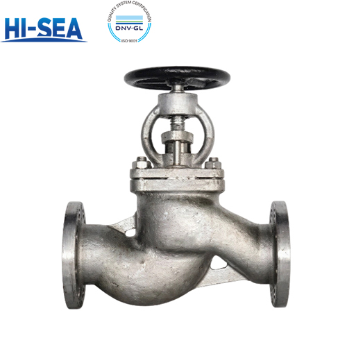
Overview
The A and AS types are straight-pattern flanged stainless steel stop check valves built for combined isolation and backflow prevention duty in shipboard piping systems handling seawater, fresh water and corrosive media.
Both share one valve body design; the difference is the flange interface — the A type is drilled to GB 569, the AS type to GB 2501. The range covers PN1.0 / PN1.6 / PN2.5 / PN4.0 / PN6.4, with DN20-500 available. Manual handwheel operation, bolted bonnet, and a metal-seated disc deliver dual performance: the handwheel can positively close the valve for isolation, while the free disc automatically closes to block reverse flow when the stem is lifted, offering predictable protection under marine corrosive service conditions.Material selection follows the medium, not the price list. Body, bonnet and all internal trim are stainless steel, typically 06Cr19Ni10 (304) or 022Cr19Ni10 (316L) for marine seawater and corrosive service; the metal-on-metal seating structure resists galling and marine corrosion without a soft seat insert. Packing and gasket are PTFE for water and general corrosive service. Stainless steel construction provides excellent resistance to pitting and crevice corrosion in seawater and chemical media.Every valve is designed, manufactured and accepted against CB/T 3943-2002, with strength, tightness, wall thickness, dimensional and geometric tolerances referenced to GB/T 600—2023. Mass is controlled to within +4 % of theoretical, castings are traceable by heat number for a minimum of three years, and marking follows GB/T 3032. Clause-by-clause verification data is listed in the compliance section below.
Basic Sructure Of SUS 304 Marine SDNR Valve Type A/AS
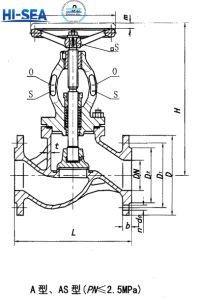
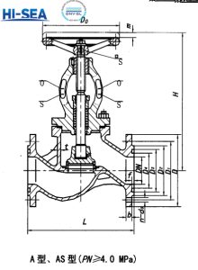
Basic parameters (CB/T 3943-2002)
| Type | Nominal Pressure PN
MPa |
Operating Temperature, ℃ | Nominal Diameter DN
mm |
Flange Standard | Applicable Media | Installation | ||||||
|---|---|---|---|---|---|---|---|---|---|---|---|---|
| ≤20 | 100 | 150 | 200 | 250 | 300 | 350 | Seawater, fresh water, fuel oil, lube oil | Horizontal / vertical, flow upward | ||||
| Maximum Allowable Working Pressure P, MPa | ||||||||||||
| A | 1.0 | 0.95 | 0.86 | 0.81 | 0.76 | 0.71 | 0.66 | 0.36 | 65~150 | GB 569 | ||
| 1.6 | 1.52 | 1.31 | 1.29 | 1.21 | 1.13 | 1.06 | 1.01 | 125, 150 | GB 569 | |||
| 2.5 | 2.38 | 2.15 | 2.01 | 1.89 | 1.77 | 1.66 | 1.59 | 20~150 | GB 569 | |||
| 4.0 | 3.80 | 3.44 | 3.22 | 3.02 | 2.83 | 2.65 | 2.54 | 65~100 | GB 569 | |||
| 6.4 | 5.69 | 5.26 | 4.96 | 4.68 | 4.41 | 4.16 | 3.92 | 20~50 | GB 569 | |||
| AS | 0.6 | 0.57 | 0.52 | 0.48 | 0.45 | 0.42 | 0.40 | 0.38 | 15~300 | GB 2501 | ||
| 1.0 | 0.95 | 0.86 | 0.81 | 0.76 | 0.71 | 0.66 | 0.63 | 200~300 | GB 2501 | |||
| 1.6 | 1.52 | 1.31 | 1.29 | 1.21 | 1.13 | 1.06 | 1.01 | 100~300 | GB 2501 | |||
| 2.5 | 2.38 | 2.15 | 2.01 | 1.89 | 1.77 | 1.66 | 1.59 | 15~300 | GB 2501 | |||
| 4.0 | 3.80 | 3.44 | 3.22 | 3.02 | 2.83 | 2.65 | 2.54 | 65~100 | GB 2501 | |||
| 6.4 | 5.69 | 5.26 | 4.96 | 4.68 | 4.41 | 4.16 | 3.92 | 20~50 | GB 2501 | |||
Working Principle
This stop check valve combines stop and check valve functions.Raise the stem: the disc opens for forward flow and automatically closes to prevent backflow upon reverse pressure.Lower the stem to press the disc tightly against the seat for positive manual shut-off.
Basic Dimensions of SUS 304 Marine SDNR Valve Type A(CB/T 3943-2002) PN 1.0, 1.6 and 2.5 MPa
| Nominal Pressure PN, MPa | Nominal Diameter DN | Structural Dimensions | Wall Thickness t | Flange | Bolt | Handwheel | Lift Range | Weight kg Type A |
|||||||
|---|---|---|---|---|---|---|---|---|---|---|---|---|---|---|---|
| L
Type A |
H≈
Type A |
D | D₁ | D₂ | d₀ | b | n Qty. | Th. | D₀ | S | m | ||||
|
|
65 | 290 | 310 | 6 | 155 | 123 | 104 | 15 | 14 | 6 | M14 | 140 | 12 | 18 | 14.5 |
| 80 | 310 | 345 | 6 | 170 | 138 | 118 | 15 | 14 | 8 | M14 | 160 | 14 | 24 | 16.8 | |
| 100 | 350 | 374 | 6 | 190 | 158 | 138 | 15 | 14 | 8 | M14 | 180 | 14 | 25 | 24.6 | |
| 125 | 400 | 426 | 7 | 215 | 183 | 164 | 15 | 14 | 10 | M14 | 200 | 17 | 32 | 34.2 | |
| 150 | 480 | 487 | 7 | 240 | 208 | 190 | 15 | 14 | 12 | M14 | 200 | 17 | 38 | 46.3 | |
| 1.6 | 125 | 400 | 465 | 8 | 225 | 187 | 168 | 17 | 15 | 10 | M16 | 250 | 22 | 32 | 44.3 |
| 150 | 480 | 524 | 8 | 255 | 217 | 196 | 17 | 15 | 12 | M16 | 280 | 24 | 38 | 56.9 | |
|
|
20 | 150 | 217 | 5 | 95 | 68 | 48 | 13 | 12 | 4 | M12 | 80 | 8 | 7 | 3.8 |
| 25 | 160 | 217 | 5 | 105 | 73 | 56 | 13 | 12 | 4 | M12 | 80 | 8 | 7 | 4.6 | |
| 32 | 180 | 236 | 5 | 115 | 83 | 64 | 13 | 12 | 4 | M12 | 100 | 9 | 9 | 6.4 | |
| 40 | 200 | 260 | 6 | 125 | 93 | 74 | 15 | 13 | 6 | M14 | 120 | 11 | 11 | 8.7 | |
| 50 | 230 | 288 | 6 | 135 | 103 | 84 | 15 | 13 | 6 | M14 | 140 | 12 | 14 | 10.9 | |
| 65 | 290 | 335 | 7 | 170 | 132 | 110 | 17 | 16 | 8 | M16 | 160 | 14 | 18 | 17.6 | |
| 80 | 310 | 366 | 7 | 185 | 147 | 126 | 17 | 16 | 8 | M16 | 200 | 17 | 24 | 24.6 | |
| 100 | 350 | 417 | 8 | 205 | 167 | 146 | 17 | 16 | 8 | M16 | 250 | 22 | 25 | 33.8 | |
| 125 | 400 | 493 | 9 | 240 | 196 | 172 | 21 | 20 | 10 | M20 | 280 | 24 | 32 | 49.2 | |
| 150 | 500 | 556 | 9 | 270 | 226 | 200 | 21 | 20 | 12 | M20 | 320 | 27 | 38 | 67.3 | |
Basic Dimensions of SUS 304 Marine SDNR Valve Type A(CB/T 3943-2002)PN 4.0 and 6.4 MPa
| Nominal Pressure PN, MPa | Nominal Diameter DN | Structural Dimensions | Wall Thickness t | Flange |
Bolt | Handwheel | Lift Range | Weight kg Type A |
||||||||||
|---|---|---|---|---|---|---|---|---|---|---|---|---|---|---|---|---|---|---|
| L Type A | H≈ Type A | D | D₁ | D₂ | D₃ | D₄ | f | d₀ | b | n Qty. | Th. | D₀ | S | m | ||||
| 4.0 | 65 | 310 | 409 | 8 | 175 | 137 | 118 | 110 | 94 | 3 | 17 | 18 | 8 | M16 | 250 | 22 | 19 | 35.2 |
| 80 | 350 | 436 | 9 | 190 | 152 | 130 | 121 | 105 | 3 | 17 | 18 | 8 | M16 | 250 | 22 | 23 | 39.1 | |
| 100 | 400 | 466 | 9 | 225 | 181 | 157 | 150 | 128 | 4 | 21 | 21 | 10 | M20 | 280 | 24 | 28 | 53.1 | |
|
|
20 | 160 | 261 | 7 | 105 | 73 | 58 | 51 | 35 | 3 | 13 | 13 | 6 | M12 | 100 | 9 | 7 | 7.7 |
| 25 | 180 | 272 | 7 | 115 | 83 | 66 | 58 | 42 | 3 | 15 | 15 | 6 | M14 | 100 | 9 | 7 | 8.7 | |
| 32 | 200 | 304 | 7 | 125 | 93 | 74 | 66 | 50 | 3 | 15 | 17 | 6 | M14 | 120 | 11 | 9 | 10.3 | |
| 40 | 230 | 334 | 7 | 145 | 107 | 84 | 76 | 60 | 3 | 17 | 19 | 6 | M16 | 160 | 14 | 12 | 17.7 | |
| 50 | 250 | 354 | 8 | 155 | 117 | 96 | 88 | 72 | 3 | 17 | 20 | 6 | M16 | 180 | 14 | 15 | 22.3 | |
Basic Dimensions of SUS 304 Marine SDNR Valve Type AS, PN 0.6, 1.0, 1.6 and 2.5 MPa
| Nominal Pressure PN, MPa | Nominal Diameter DN | Structural Dimensions | Wall Thickness t | Flange |
Bolt | Handwheel | Lift Range | Weight kg
Type AS |
|||||||
|---|---|---|---|---|---|---|---|---|---|---|---|---|---|---|---|
| L Type AS | H≈ Type AS | D | D₁ | D₂ | d₀ | b | n Qty. | Th. | D₀ | S | m | ||||
|
0.6 |
15 | 130 | 217 | 4 | 80 | 55 | 40 | 11 | 12 | 4 | M10 | 80 | 8 | 7 | 3.6 |
| 20 | 150 | 217 | 4 | 90 | 65 | 50 | 11 | 14 | 4 | M10 | 80 | 8 | 7 | 4.4 | |
| 25 | 160 | 217 | 4 | 100 | 75 | 60 | 11 | 14 | 4 | M10 | 80 | 8 | 7 | 5.1 | |
| 32 | 180 | 236 | 5 | 120 | 90 | 70 | 14 | 16 | 4 | M12 | 100 | 9 | 9 | 6.4 | |
| 40 | 200 | 260 | 5 | 130 | 100 | 80 | 14 | 16 | 4 | M12 | 120 | 11 | 11 | 8.5 | |
| 50 | 230 | 288 | 6 | 140 | 110 | 90 | 14 | 16 | 4 | M12 | 140 | 12 | 14 | 10.6 | |
| 65 | 290 | 335 | 6 | 160 | 130 | 110 | 14 | 16 | 4 | M12 | 160 | 12 | 18 | 16.7 | |
| 80 | 310 | 362 | 6 | 190 | 150 | 128 | 14 | 18 | 8 | M16 | 160 | 14 | 24 | 22.2 | |
| 100 | 350 | 417 | 7 | 210 | 170 | 148 | 18 | 20 | 8 | M16 | 180 | 14 | 25 | 33.4 | |
| 125 | 400 | 493 | 7 | 240 | 200 | 178 | 18 | 20 | 8 | M16 | 200 | 17 | 32 | 45.1 | |
| 150 | 480 | 556 | 7 | 265 | 225 | 202 | 18 | 22 | 8 | M16 | 200 | 17 | 38 | 67.5 | |
| 200 | 600 | 675 | 9 | 320 | 280 | 258 | 22 | 24 | 12 | M20 | 250 | 22 | 50 | 98.3 | |
| 250 | 730 | 721 | 9 | 375 | 335 | 312 | 22 | 24 | 12 | M20 | 280 | 24 | 60 | 162.0 | |
| 300 | 850 | 821 | 9 | 440 | 395 | 365 | 24 | 26 | 12 | M20 | 320 | 27 | 75 | 220.0 | |
| 1.0 | 200 | 600 | 621 | 10 | 340 | 295 | 268 | 22 | 24 | 8 | M20 | 360 | 27 | 50 | 107.0 |
| 250 | 730 | 721 | 11 | 395 | 350 | 320 | 22 | 26 | 12 | M20 | 450 | 32 | 60 | 165.0 | |
| 300 | 850 | 821 | 11 | 445 | 400 | 370 | 22 | 26 | 12 | M20 | 500 | 36 | 75 | 223.0 | |
|
1.6 |
100 | 350 | 417 | 8 | 220 | 180 | 158 | 18 | 22 | 8 | M16 | 250 | 22 | 25 | 35.4 |
| 125 | 400 | 493 | 8 | 250 | 210 | 184 | 18 | 22 | 8 | M16 | 280 | 24 | 32 | 50.5 | |
| 150 | 480 | 556 | 9 | 285 | 240 | 212 | 22 | 24 | 8 | M20 | 320 | 27 | 38 | 67.3 | |
| 200 | 600 | 621 | 9 | 340 | 295 | 268 | 22 | 24 | 8 | M20 | 450 | 32 | 50 | 121.0 | |
| 250 | 730 | 721 | 11 | 405 | 355 | 320 | 26 | 26 | 12 | M24 | 500 | 36 | 60 | 167.2 | |
| 300 | 850 | 821 | 11 | 460 | 410 | 370 | 26 | 28 | 12 | M24 | 500 | 36 | 75 | 215.0 | |
|
2.5 |
15 | 130 | 217 | 5 | 95 | 65 | 47 | 14 | 14 | 4 | M12 | 80 | 8 | 7 | 4.6 |
| 20 | 150 | 217 | 5 | 105 | 75 | 58 | 14 | 16 | 4 | M12 | 80 | 8 | 7 | 4.9 | |
| 25 | 160 | 217 | 5 | 115 | 85 | 68 | 14 | 16 | 4 | M12 | 80 | 8 | 7 | 5.7 | |
| 32 | 180 | 236 | 6 | 140 | 100 | 78 | 18 | 18 | 4 | M16 | 100 | 9 | 9 | 8.9 | |
| 40 | 200 | 260 | 6 | 150 | 110 | 88 | 18 | 18 | 4 | M16 | 120 | 11 | 11 | 10.6 | |
| 50 | 230 | 288 | 7 | 165 | 125 | 102 | 18 | 20 | 4 | M16 | 140 | 12 | 14 | 14.2 | |
| 65 | 290 | 335 | 7 | 185 | 145 | 122 | 22 | 22 | 8 | M16 | 160 | 14 | 18 | 21.9 | |
|
2.5 |
80 | 310 | 366 | 7 | 200 | 160 | 133 | 22 | 24 | 8 | M20 | 200 | 17 | 24 | 28.4 |
| 100 | 350 | 427 | 8 | 235 | 190 | 158 | 22 | 24 | 8 | M20 | 250 | 22 | 25 | 39.5 | |
| 125 | 400 | 493 | 8 | 270 | 220 | 184 | 26 | 26 | 8 | M20 | 280 | 24 | 32 | 57.3 | |
| 150 | 480 | 556 | 8 | 300 | 250 | 212 | 26 | 28 | 8 | M24 | 320 | 27 | 38 | 75.9 | |
| 200 | 600 | 621 | 10 | 360 | 310 | 278 | 30 | 30 | 12 | M24 | 450 | 32 | 50 | 129.0 | |
| 250 | 730 | 721 | 11 | 425 | 370 | 335 | 30 | 32 | 12 | M27 | 500 | 36 | 60 | 167.2 | |
| 300 | 850 | 821 | 11 | 485 | 430 | 390 | 30 | 34 | 16 | M27 | 500 | 36 | 75 | 215.0 | |
Basic Dimensions of SUS 304 Marine SDNR Valve Type AS, PN 0.6, 1.0, 1.6 and 2.5 MPa PN 4.0 and 6.4 MPa
| Nominal Pressure PN, MPa | Nominal Diameter DN | Structural Dimensions | Wall Thickness t | Flange |
Bolt | Handwheel | Lift Range | Weight kg Type AS |
||||||||||
|---|---|---|---|---|---|---|---|---|---|---|---|---|---|---|---|---|---|---|
| L Type AS | H≈ Type AS | D | D₁ | D₂ | D₃ | D₄ | f | d₀ | b | n Qty. | Th. | D₀ | S | m | ||||
|
4.0 |
65 | 290 | 409 | 8 | 185 | 145 | 122 | 110 | 94 | 3 | 18 | 22 | 8 | M16 | 250 | 22 | 19 | 37.8 |
| 80 | 310 | 436 | 9 | 200 | 160 | 133 | 121 | 105 | 3 | 18 | 24 | 8 | M16 | 250 | 22 | 23 | 42.9 | |
| 100 | 350 | 466 | 9 | 235 | 190 | 158 | 150 | 128 | 3 | 22 | 24 | 8 | M20 | 280 | 24 | 28 | 54.1 | |
|
|
20 | — | 261 | 7 | 130 | 90 | 58 | 51 | 35 | 3 | 18 | 22 | 4 | M16 | 100 | 9 | 7 | 9.3 |
| 25 | 230 | 272 | 7 | 140 | 100 | 68 | 58 | 42 | 3 | 18 | 24 | 4 | M16 | 100 | 9 | 7 | 11.0 | |
| 32 | — | 304 | 7 | 155 | 110 | 78 | 66 | 50 | 3 | 18 | 24 | 4 | M16 | 120 | 11 | 9 | 13.1 | |
| 40 | 260 | 334 | 7 | 170 | 125 | 88 | 76 | 60 | 3 | 22 | 26 | 4 | M20 | 160 | 14 | 12 | 21.7 | |
| 50 | 300 | 354 | 8 | 180 | 135 | 102 | 88 | 72 | 3 | 22 | 26 | 4 | M20 | 180 | 14 | 15 | 27.2 | |
Materials of Principle Parts(CB/T 3943-2002)
| Part Name | Material | ||
|---|---|---|---|
| Name | Grade | Standard No. | |
| Valve body, bonnet, disc | Stainless steel | ZG0Cr18Ni9 | GB/T2100-1980 |
| ZG00Cr17Ni14Mo3 | Material and Welding Code (1998) | ||
| Valve stem, fasteners | Stainless steel | 0Cr13 | GB/T1220-1992 |
| Packing, gasket | PTFE | — | — |
| Hardfaced seat for PN≥4.0 MPa | Cobalt‑chromium‑tungsten hard alloy | — | — |
Selection & Installation Key Points
1.Selection: For seawater, fresh water and compatible low-temperature media, PN ≤6.4 MPa. Complies with CB/T3943-2002 Marine Flanged Stainless Steel Stop-Check Valve standard. Select according to pipeline size; confirm stainless steel wetted parts for marine corrosion resistance.
2.Installation orientation: Can be installed horizontally or vertically. Keep the valve mark of flow direction consistent with pipeline flow direction. Reserve sufficient surrounding space for adjustment and maintenance. FORBIDDEN: Do not use for throttling for long time.
3.Sealing pair: Cobalt-chromium-tungsten hard alloy hardfaced sealing surface for PN≥4.0MPa, suitable for water and low-temperature medium. Avoid sand, metal debris and hard impurities scratching the sealing surface.
4.Temp-pressure: Rated pressure applies at normal temperature. Temperature rise affects sealing performance; keep operating pressure and temperature below the rated value of selected grade. This valve adapts to working temperature down to -165℃.
5.Flow & clearance: Unidirectional flow. It can cut off flow manually and prevent backflow automatically. Isolate upstream medium by closing the front stop valve before disassembly; avoid medium leakage.
Why this SUS 304 Marine SDNR Valve
One integrated structure: The stainless steel valve body and bonnet are the main components. Rotating the handwheel drives the stem and disc to open or close the passage, and it can automatically block reverse flow when medium backflows. Flange connection complying with GB/T569, compact structure, reliable sealing and easy operation. It is a combined cut-off & non-return component for marine seawater, fresh water and low-temperature pipelines of chemical tankers, LNG carriers and vessels. The internal flow channel is specially designed for ship service system. The hard alloy sealing pair features excellent seawater corrosion resistance, good low-temperature toughness, long service life and good tightness. The valve can be disassembled for inspection and replacement of wearing parts, without heavy dismantling of adjacent pipelines. Wetted materials: ZG0Cr18Ni9 / ZG00Cr17Ni14Mo3 stainless steel body & bonnet, 0Cr13 stem and fasteners, PTFE packing and gasket, cobalt-chromium-tungsten hard alloy hardfacing for PN≥4.0MPa. What it is not: a throttling component. It is only for medium cut-off and backflow prevention; long-time throttling will cause rapid wear to the sealing surface.