
Overview
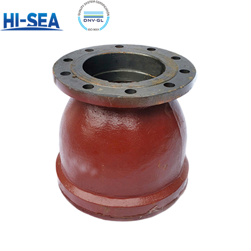
The B/BS type marine gooseneck air pipe head conforming to CB/T3594‑94 is a flanged cast ventilating fitting built for tank venting duty on oil tanks, ballast tanks, fresh water tanks and other liquid tank compartments of ships and offshore installations. Type B adopts flange dimensions complying with GB 569, while Type BS adopts flange dimensions complying with GB 2501. All variants share one streamlined shell design with fixed flange connections. The standard size range covers DN50, DN65, DN80, DN100, DN125, DN150, DN200 and DN250. Its integrated gooseneck‑shaped cavity delivers dual performance: the curved internal passage permits free air flow in and out during tank filling and discharging to balance tank pressure, while the inherent baffled structure blocks rainwater, splashing seawater and deck spray from entering the tank compartment, offering reliable tank interior protection and avoiding medium contamination under marine corrosive service conditions. Material selection follows the medium and working environment. Body is normally cast iron; internal flow surface is coated with anti‑corrosive paint for enhanced rust resistance against marine atmosphere and condensed water; the smooth internal channel reduces air flow resistance and avoids debris accumulation. Gaskets are oil‑resistant or water‑resistant composite material selected according to whether the tank carries oil or water medium. Cast metal construction provides reliable mechanical strength and good vibration resistance under deck operating conditions. Every air pipe head is designed, manufactured and accepted against CB/T3594‑94, with strength, wall thickness, dimensional and geometric tolerances referenced to GB/T 600. Mass is controlled within agreed tolerance, castings are traceable by heat number for a minimum of three years, and marking follows GB/T 3032. Clause‑by‑clause verification data is listed in the compliance section below.
Basic Sructure of Air Pipe Joint Type B/BS
Basic parameters (CB/T3594)
| Type | Name | Nominal Diameter DN
mm |
Scope of Application |
|---|---|---|---|
| A, AS | Cap-type air pipe head | 50 ~ 250 | Upper end of air pipes for oil and water tanks |
| B, BS | Gooseneck-type air pipe head | 50 ~ 250 | Upper end of air pipes for oil and water tanks |
| C, CS | Sounding & venting combined air pipe head | 50 ~ 100 | Upper end of air pipes for oil and water tanks |
| D, DS | Float-type air pipe head for oil tanks | 50 ~ 350 | Upper end of air pipes for oil tanks |
| E, ES | Float-type air pipe head for water tanks | 50 ~ 350 | Upper end of air pipes for water tanks |
| FS | Float-ball air pipe head for oil and water tanks | 50 ~ 350 | Upper end of air pipes for oil and water tanks |
Working Principle
The B/BS gooseneck air pipe head is a passive ventilating fitting without moving components. When liquid is filled into or discharged from the tank, the change of liquid level alters the internal pressure of the tank. Positive pressure inside the tank will push air outwards through the curved gooseneck passage; negative pressure will draw ambient air into the tank. The free exchange of air balances the tank pressure and prevents vacuum or overpressure that may damage the tank structure.
The bent gooseneck structure acts as a baffle. Rainwater, splashing seawater and deck spray are intercepted by the curved cavity and drain back to the deck, rather than flowing into the tank. It keeps contaminants out while maintaining unobstructed ventilation.
This air pipe head has no shut‑off function. It shall not be used to isolate the tank compartment.
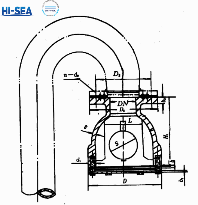
Basic Dimensions of Type B/BS Air Pipe Joint(unit:mm/kg)
| Nominal Diameter DN | Head | Sphere Diameter S | Wall Thickness δ | Flange Connection Dimensions | Gasket Thickness b₁ | Grating Thickness b | Guide Rib | Weight kg | |||||||
|---|---|---|---|---|---|---|---|---|---|---|---|---|---|---|---|
| Height H₁ | Diameter D | Outer Diameter D₂ | Pitch Circle Diameter D₃ | Thickness b₂ | Bolt Hole | Spacing L | Quantity n₂ (pcs) | Cast Iron | Cast Steel | ||||||
| n (pcs) | d₀ | ||||||||||||||
| 50 | 120 | 140 | 70 | 7 | 135 | 103 | 15 | 6 | 15 |
6 |
3 |
78 |
4 |
5.20 | 5.70 |
| 140 | 110 | 16 | 4 | 14 | 5.82 | 5.99 | |||||||||
| 65 | 150 | 175 | 80 |
|
155 | 123 | 14 | 6 | 15 | 88 | 7.29 | 8.20 | |||
| 160 | 130 | 16 | 4 | 14 | 7.47 | 8.47 | |||||||||
| 80 | 170 | 195 | 100 | 170 | 138 | 14 | 8 | 15 | 108 | 8.20 | 9.50 | ||||
| 190 | 150 | 18 | 4 | 18 | 9.66 | 9.96 | |||||||||
| 100 | 195 | 235 | 125 | 190 | 158 | 14 | 8 | 15 | 133 | 16.10 | 16.20 | ||||
| 210 | 170 | 18 | 4 | 18 | 16.69 | 16.79 | |||||||||
| 150 | 230 | 280 | 175 |
11 |
240 | 208 | 14 | 12 | 15 | 5 | 183 | 18.40 | 18.40 | ||
| 265 | 225 | 20 | 8 | 18 | 20.40 | 21.40 | |||||||||
| 200 | 270 | 320 | 220 | 295 | 264 | 15 | 12 | 15 | 6 |
228 | 22.10 | 23.80 | |||
| 320 | 280 | 22 | 8 | 18 | 23.18 | 24.58 | |||||||||
| 250 | 310 | 370 | 270 | 12 | 365 | 327 | 16 | 14 | 17 | 278 | 28.70 | 29.20 | |||
| 375 | 335 | 24 | 12 | 18 | 32.29 | 35.79 | |||||||||
Note: The upper values in the flange connection dimension column comply with GB 569, and the lower values comply with GB 2501.
Material of main Parts(CB/T3594)
| Item | Part Name | Material | Grade |
|---|---|---|---|
| 1 | Body (Gooseneck Housing) | Grey Cast Iron / Cast Steel | HT200 / ZG200‑400 |
| 2 | Grating | Carbon Steel | Q235‑B |
| 3 | Guide Rib | Carbon Steel | Q235‑B |
| 4 | Bolts & Fasteners | Stainless Steel | SUS304 |
| 5 | Gasket | Oil‑Resistant Rubber | NBR |
Selection & Installation Key Points
1.Selection: For oil tank, water tank and compatible marine media. Complies with CB/T3594‑94 Marine Gooseneck Air Pipe Head standard. Select according to tank capacity and pipeline size; confirm cast iron or cast steel body options for marine corrosion resistance.
2.Installation orientation: Install vertically on the upper end of tank vent pipe. Keep the gooseneck outlet facing away from deck splash direction. Reserve sufficient surrounding space for inspection and cleaning. FORBIDDEN: Do not install horizontally or upside down; do not use as a shut‑off valve or throttling device.
3.Internal structure: Fixed grating and guide ribs are integrated inside for debris blocking. No moving parts. Avoid welding slag, paint debris and hard impurities left inside the flow channel to prevent ventilation blockage.
4.Temp & medium: This fitting is suitable for normal atmospheric venting of marine oil and water tanks. Working temperature range: -20℃ to +80℃. It is not applicable for flammable gas service requiring flame arrestor function.
5.Flow & clearance: One‑way free ventilation for pressure balancing. It can exhaust air when tank overpressure occurs and inhale air automatically when tank vacuum forms. Isolate upstream medium by closing the isolating valve before disassembly; avoid liquid overflow or seawater ingress.
Why this Marine Gooseneck Air Pipe Head (CB/T3594‑94)
One integrated structure: The cast steel or grey cast iron housing is the main component. The curved gooseneck cavity realizes air exchange and splash water blocking without any moving parts. Flange connection complying with GB 569 or GB 2501, compact structure, reliable performance and maintenance‑friendly. It is a passive venting component for oil tanks, ballast tanks and fresh water tanks of bulk carriers and vessels. The internal flow channel is specially designed for ship tank vent system. Cast iron or cast steel body features excellent seawater corrosion resistance, low flow resistance and stable long‑term ventilation performance.The air pipe head can be disassembled for inspection and cleaning of grating, without heavy dismantling of adjacent pipelines.
Wetted materials: HT200 grey cast iron / ZG200‑400 cast steel body, Q235‑B carbon steel grating and guide ribs, NBR rubber gasket. What it is not: A shut‑off valve or flame arrester. It is only for tank pressure balance and splash‑water protection; long‑term exposure to oil vapour will accelerate rubber gasket ageing.