
Overview
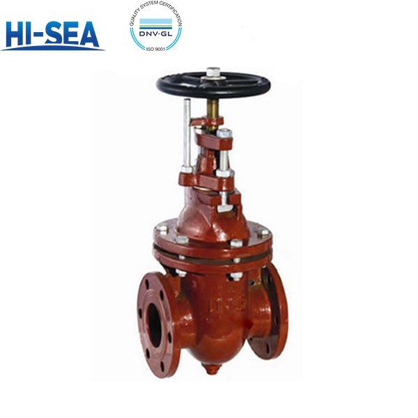
Flanged Cast Iron Gate Valve is a manually operated isolation valve specially designed for marine piping systems. It provides full‑open / full‑closed shut‑off function, not suitable for throttling service. It adopts CB/T465‑1995 standard. PN0.6 for DN50‑DN150, PN0.4 for DN175‑DN300, PN0.25 for DN350‑DN500. Suitable for fresh water, seawater and lubricating oil up to 120℃. It has cast iron body and bonnet, metal hard sealing face, bronze stem and handwheel operation, with PTFE or rubber gasket as specified. It can be installed horizontally or vertically, with no restriction on flow direction. Each valve is pressure‑tested per GB/T 600. Confirm nominal diameter, flange type and gasket material before ordering; it shall not be used for flow regulation, otherwise sealing face may be damaged.
Basic Sructure of Cast Iron Flanged Gate Valve Type A/AS
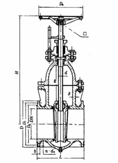
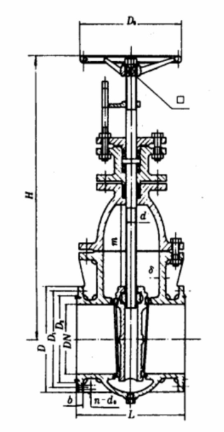
Basic parameters (CB/T465-1995)
| Type | PN (MPa) | DN (mm) | Medium | Working Temp | Flange Standard | Installation |
|---|---|---|---|---|---|---|
| A、AS | 0.6 | 50~150 | Fresh water, seawater, lubricating oil | ≤120℃ | CB/T465‑1995 | Horizontal or vertical, no restriction on flow direction |
| A、AS | 0.4 | 175~300 | Fresh water, seawater, lubricating oil | ≤120℃ | CB/T465‑1995 | Horizontal or vertical, no restriction on flow direction |
| AS | 0.25 | 350~500 | Fresh water, seawater, lubricating oil | ≤120℃ | CB/T465‑1995 | Horizontal or vertical, no restriction on flow direction |
Working Principle
Rotate the handwheel to lift or lower the gate via stem threads, opening or closing the flow passage. The rising stem visually indicates the valve opening. It is only used for full open and full close, not for flow regulation.
Basic dimensions (CB/T465-1995)
Type A
| PN
(MPa) |
DN
(mm) |
Structure dimension | flange | bolt | ||||||
| L | H | D | D1 | D2 | b | d0 | n | Th. | ||
| 0.6 | 50 | 190 | 340 | 135 | 103 | 84 | 16 | 15 | 6 | M14 |
| 65 | 200 | 372 | 155 | 123 | 104 | 15 | 15 | 6 | M14 | |
| 80 | 220 | 430 | 170 | 138 | 118 | 15 | 15 | 8 | M14 | |
| 100 | 220 | 460 | 190 | 158 | 138 | 15 | 15 | 8 | M14 | |
| 125 | 242 | 528 | 215 | 183 | 164 | 15 | 15 | 10 | M14 | |
| 150 | 248 | 566 | 240 | 208 | 190 | 16 | 15 | 12 | M14 | |
| 0.4 | 175 | 268 | 630 | 270 | 238 | 221 | 16 | 15 | 12 | M14 |
| 200 | 278 | 685 | 295 | 264 | 247 | 16 | 15 | 12 | M14 | |
| 250 | 310 | 755 | 365 | 327 | 306 | 18 | 17 | 14 | M16 | |
| 300 | 345 | 835 | 430 | 386 | 360 | 19 | 21 | 14 | M20 | |
Type AS
| PN
(MPa) |
DN
(mm) |
Structure dimension | flange | bolt | ||||||
| L | H | D | D1 | D2 | b | d0 | n | Th. | ||
| 0.6 | 50 | 178 | 340 | 140 | 110 | 90 | 16 | 14 | 4 | M12 |
| 65 | 190 | 372 | 160 | 130 | 110 | 16 | 14 | 4 | M12 | |
| 80 | 203 | 430 | 190 | 150 | 128 | 18 | 18 | 4 | M16 | |
| 100 | 229 | 460 | 210 | 170 | 148 | 18 | 18 | 4 | M16 | |
| 125 | 254 | 528 | 240 | 200 | 178 | 20 | 18 | 8 | M16 | |
| 150 | 267 | 566 | 265 | 225 | 202 | 20 | 18 | 8 | M16 | |
| 0.4 | 175 | 292 | 630 | 295 | 255 | 232 | 22 | 18 | 8 | M16 |
| 200 | 292 | 685 | 320 | 280 | 258 | 22 | 18 | 8 | M16 | |
| 250 | 330 | 755 | 375 | 335 | 312 | 24 | 18 | 12 | M16 | |
| 300 | 356 | 835 | 440 | 395 | 365 | 24 | 22 | 12 | M20 | |
| 0.25 | 350 | 381 | 1050 | 490 | 445 | 415 | 26 | 22 | 12 | M20 |
| 400 | 406 | 1145 | 540 | 495 | 465 | 28 | 22 | 16 | M20 | |
| 450 | 432 | 1330 | 595 | 550 | 520 | 28 | 22 | 16 | M20 | |
| 500 | 457 | 1420 | 645 | 600 | 570 | 30 | 22 | 20 | M20 | |
Materials of principal parts(CB/T465-1995)
| Part Name | Material | ||
|---|---|---|---|
| Name | Grade | Standard No. | |
| Body, Bonnet, Valve Disc | Grey Cast Iron | HT200 | GB 9439-88 |
| Stem, Square Nut | Aluminium Bronze | QAl9-2 | GB 4429-84 |
Selection & Installation Key Points
1.Selection: For liquid only (fresh water, seawater, lube oil), ≤120℃. Select valve type according to medium and flow rate; confirm material code (T/H/N) for corrosion resistance.
2.Installation orientation: Can be installed horizontally or vertically on pipelines. Reserve sufficient space for handwheel operation. FORBIDDEN: Do not use for flow throttling.
3.Seat: Hard metal sealing, suitable for clean liquid without large solid particles.
4.Temp-pressure: Rated pressure applies at normal temperature. Temperature rise affects sealing performance; keep operating pressure below nominal pressure.
5.Flow & clearance: Bidirectional flow, no flow direction restriction. Keep surrounding space available for disassembly and maintenance; avoid impurities damaging the sealing faces.
Why this valve
One integrated structure: the wedge gate is the closing element. Rotating the handwheel converts rotary motion into linear movement of the stem to lift or lower the gate for opening and closing. One flange connection, one set of sealing pairs, fewer spare parts. It is manually operated with no automatic opening or closing. The rising stem directly shows the opening status for visual check. The full-bore straight passage brings low flow resistance. The simple wedge gate structure brings easy maintenance. The valve can be disassembled for inspection, gate and sealing face repair, with direct access to internal parts; no heavy dismantling of adjacent pipelines. Wetted materials are optional on order: cast iron HT200, cast bronze or stainless steel for body, bronze or stainless steel valve stem, cast bronze or stainless steel gate, suitable for fresh water, seawater and lube oil below 80℃. What it is not: a control valve or check valve. It is only for full open or full close; it cannot stay partially open for throttling, and partial opening will cause rapid wear and vibration of the sealing surface.