Marine Oil Water Separator
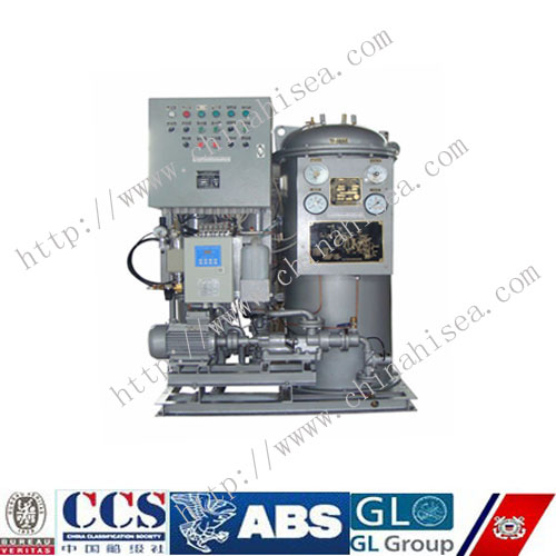
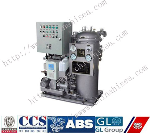
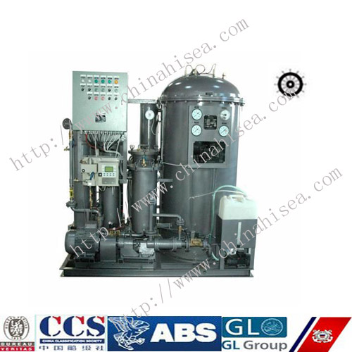
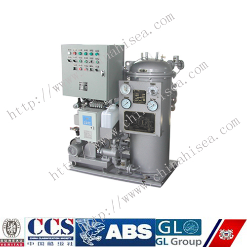
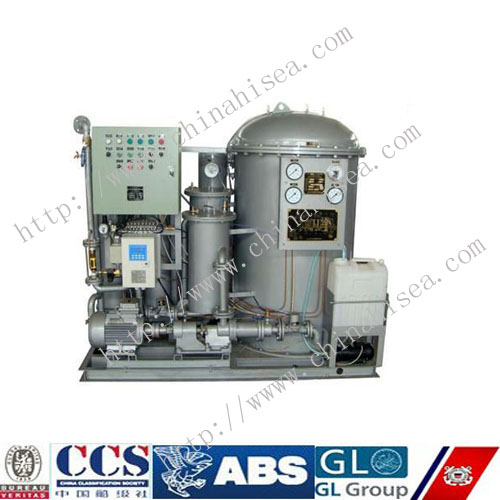
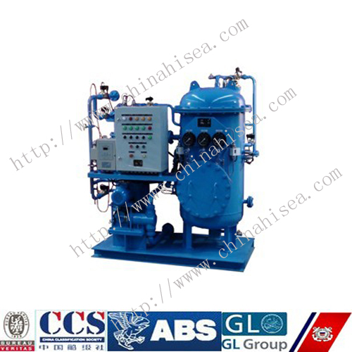
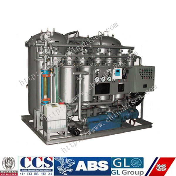
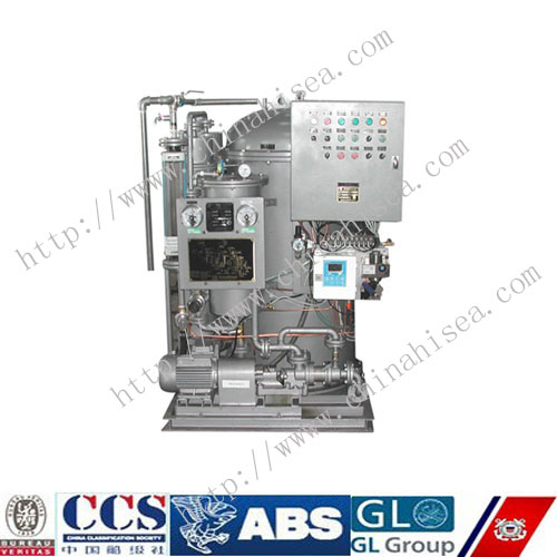
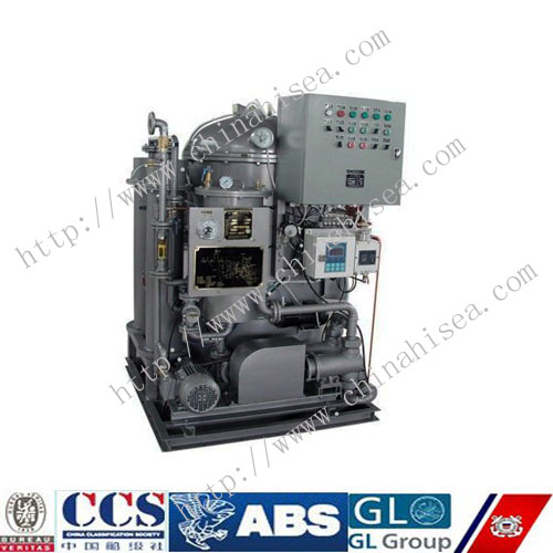
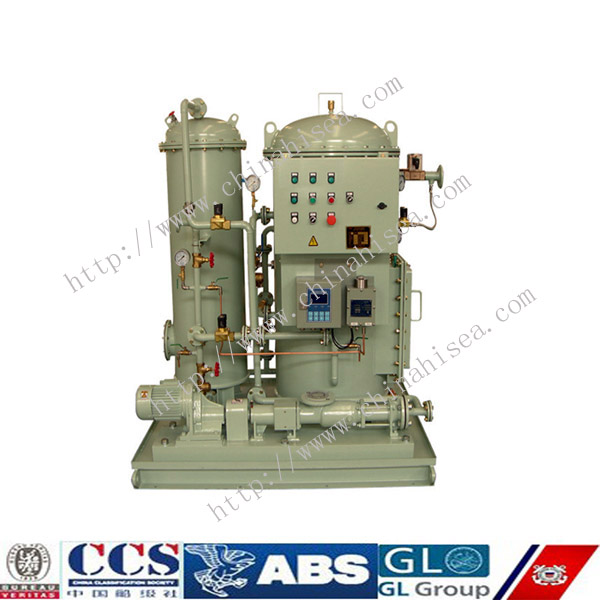
1. Marine Oil Water Separator Outline Drawing
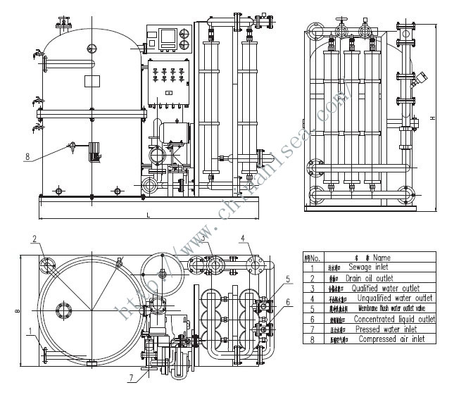
Marine Oil Water Separator is the succeed new product on the basement of several years’ experience and domestic and foreign advanced technical. It can be used in treatment of marine oil sewage as well as oil process in industries and minings, and oil sewage where emulsification oil content is very high. The performance complies with marine with oil effluent standard specified in IMO and oil sewage effluent standard of marine, industries and minings specified by Chinese Government, complying with requirements of IMO-MEPC107(49) Resolution.
2. Marine Oil Water Separator System Principle:
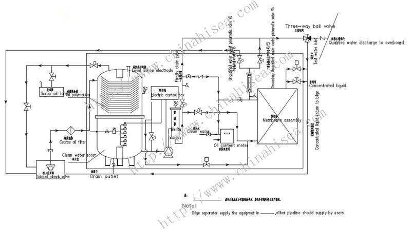
Primary bilge separator, secondary emulsification oil bilge separator (integrate room), plunger pump, electric control box, oil content warning recorder, fine filter, pneumatic valve, electromagnetism valve are installed on the common base.
Separator adopts international advanced vacuum suction combined with oil drop polymerization (to be coarse) technical to disposal oil sewage, matched plunger pump pumped treated water at purified room of primary separator to produce vacuum, bilge water flow into oil separator through primary filter, great drop floats on the top, remained sewage contained small drop flow into special converger where small drop in oil sewage grows into big one and floats on the top room. Qualified water flows through discharge outlet plunger pump to overboard by primary outlet valve.
When primary separator discharges unqualified water on running situations, oil content warning recorder sends out signal, primary effluent leads automatically to secondary emulsification oil separator for further membrane treatment. Qualified water is discharged overboard by secondary drain valve. Every other 30 minutes (interval time is regulated on process effects by users), primary separator restarts to recover the operations above. When secondary emulsification oil separator is out of order and the secondary effluent is unqualified, oil content warning recorder sends out signal again, returned pneumatic valve(returned electromagnetism valve) opened, and draining pneumatic valve closed to dispose treated water again.
When process situation is secondary membrane separation, draining regulated valve (concentrated liquid circumfluence valve) on the top of emulsification oil separator is normal open, parts of oil sewage contained fine solid SS is returned to bilge by this valve to reduce jam resistance. The open capacity is regulated to 20% rated capacity by observing flow meter.
Oil detected electrode sends out signal when separated oil is centralized to some certain extent on the top of primary separator, then plunger pump stops, primary outlet pneumatic valve, secondary inlet pneumatic valve closed, and bilge water stops entering separator, no water is drained. Oil draining pneumatic valve, pressure water pneumatic valve opened at the same time. Pressure water (clean sea water or fresh water) enters bottom of separator by pressure water pneumatic valve, flows conversed through oil converger for back flushing, and oil inside separator discharges to oil tank by oil draining pneumatic valve. Pneumatic valve is controlled by electromagnetism valve to control open and close of pneumatic valve. When oil is drained out, oil draining pneumatic valve and pressure water pneumatic valve is closed automatically, plunger pump starts and relative valves opened automatically.
3. Marine Oil Water Separator Technical Data:
|
Model |
ZYFM -0.25 |
ZYFM -0.50 |
ZYFM -1.00 |
ZYFM -2.00 |
ZYFM -3.00 |
ZYFM -4.00 |
ZYFM -5.00 |
|
|
Treated Capacity (m3/h) |
0.25 |
0.50 |
1.00 |
2.00 |
3.00 |
4.00 |
5.00 |
|
|
Outline Dimension (mm) |
800×760 ×1600 |
1350×700 ×1700 |
1450×700 ×1600 |
1800×1000 ×1830 |
2200×1100 ×1830 |
2300×1200 ×1830 |
2400×1400 ×1830 |
|
|
Oil Content in Effluent Water |
≤15ppm |
|||||||
|
Liquid Draining Control |
Auto. And Manual |
|||||||
|
Heating Style |
Electric Heating |
|||||||
|
Pump Type |
DZ-250 |
DZ-500 |
DZ-1000 |
DZ-2000 |
DZ-3000 |
DZ-4000 |
DZ-5000 |
|
|
Speed of Motor (γ/min) |
1400 |
1400 |
1400 |
1400 |
1400 |
1400 |
1400 |
|
|
Power of Motor (kW) |
0.18 |
0.25 |
0.37 |
0.75 |
1.1 |
1.5 |
1.5 |
|
|
Total Power (kW) |
2.5 |
2.5 |
7 |
7.5 |
8 |
8 |
8 |
|
|
Connected Dimension (DN) |
Sewage Inlet |
25 |
25 |
40 |
40 |
50 |
65 |
65 |
|
Effluent Outlet |
25 |
25 |
40 |
40 |
50 |
65 |
65 |
|
|
Oil Drain |
20 |
25 |
25 |
25 |
40 |
50 |
50 |
|
|
Pressed Water Inlet |
20 |
25 |
25 |
25 |
40 |
50 |
50 |
|
|
Voltage |
AC 380V/50Hz/3Φ (Optional) |
|||||||
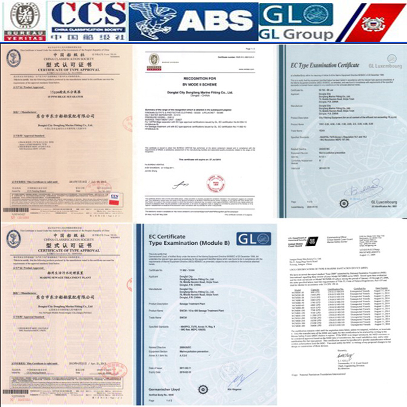
4. Marine Oil Water Separator Certificate:
5. Marine Oil Water Separator Workshop:
Society certificates


CONTACT WITH US NOW