Overview
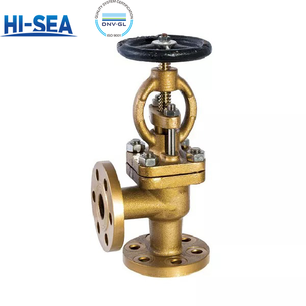
The B/BS series are right-angle (90-degree), handwheel-operated marine bronze flanged stop valves, designed for isolation and flow diversion where piping requires a 90-degree turn in shipboard systems handing fresh water, seawater, lube oil, fuel oil, air, and steam up to 250 °C. Type B uses flange connection dimensions and sealing faces according to CB/T 4196—2011; Type BS uses GB/T 9124.1—2019. The PN/DN coverage matches the A/AS series (PN6 to PN25, DN15 to DN250 depending on type); exact size combinations are listed in the specification tables.
The valve materials are identical to the straight-through series: bronze body, bonnet, disc and packing nut, aluminium bronze stem, PTFE braided or flexible graphite packing, PTFE or flexible graphite gasket, stainless steel studs/nuts, and a CF8 handwheel with open/close indication. For seawater service, nickel-aluminium bronze is recommended; for fuel oil and steam, flexible graphite packing and gasket should be selected. The standard also notes the de-alloying corrosion risk of aluminium bronze in seawater, and anti-de-alloying treatment can be provided on request.
The product standard is GB/T 587—2026. Strength and tightness follow GB/T 600—2023. BS-type structural length tolerance follows GB/T 11698—2026; B-type follows the construction drawing. Theoretical weight is based on cast tin bronze (nickel-aluminium bronze is 8% lighter), with positive deviation not exceeding 4%. Castings require at least three heat-numbered test bars per heat, retained for not less than 3 years. Type inspection uses three samples; factory inspection, marking, packaging, and storage follow the above standards. Specific clause references and test pressure values are listed in the Compliance and Testing section below.
Basic Sructure of Marine Bronze Flanged Stop Valve Type B/BS
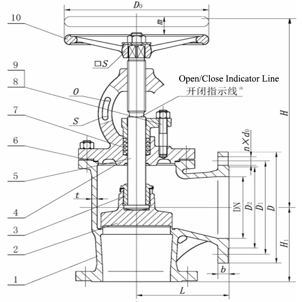
| Type and application scope of Type B / BS stop valves(GB/T 587—2026) | |||||
|---|---|---|---|---|---|
| Type | Body design | Flange dimensions & sealing face | Face-to-face tolerance | Service media and temperature | Mating flange |
| B | Angle type, 90° (right-angle globe) | CB/T 4196—2011 | As specified on the construction drawing |
Fresh water, sea water, lube oil, fuel oil, air and steam up to 250 °C |
CB-series marine flanges |
| BS | Angle type, 90° (right-angle globe) | GB/T 9124.1—2019 (PN series) | GB/T 11698—2026 | GB-series steel pipe flanges | |
| Angle pattern replaces one 90° elbow at a pipe corner, giving a shorter and stiffer run; inlet and outlet flanges are perpendicular. The matching straight-through versions are Types A / AS. Strength and tightness per GB/T 600—2023, 4.14 and 4.15; wall thickness 4.2; dimensional tolerances 4.5; geometrical tolerances 4.7. | |||||
| Basic parameters, Type B / BS(GB/T 587—2026) | ||||
|---|---|---|---|---|
| Type | PN | Max. working pressure (MPa) | Size range (DN) | Service media |
|
B |
10 | 1.0 | 65 – 250 |
Fresh water, sea water, lube oil, fuel oil, air; steam up to 250 °C |
| 16 | 1.6 | 125, 150 | ||
| 25 | 2.5 | 20 – 125 | ||
|
BS |
6 | 0.6 | 15 – 150 | |
| 16 | 1.6 | 65 – 150 | ||
| 25 | 2.5 | 15 – 125 | ||
| PN–DN coverage is identical to the straight-through Types A / AS. Type B has no PN6 rating; Type BS has no PN10 rating. Body material: Q1 cast tin bronze, Q2 nickel-aluminium bronze. | ||||
| Basic dimensions, Type B — angle pattern, CB/T 4196—2011 flanges(GB/T 587—2026) | ||||||||||||||
|---|---|---|---|---|---|---|---|---|---|---|---|---|---|---|
| PN | DN | L | H1 | H≈ | t | D | D1 | D2 | d0 | b | n | Thread | Lift | Weight (kg) |
|
10 |
65 | 115 | 115 | 277 | 6 | 155 | 123 | 104 | 15 | 14 | 6 | M14 | 19 | 14.7 |
| 80 | 125 | 125 | 304 | 6 | 170 | 138 | 118 | 15 | 14 | 8 | M14 | 26 | 18.1 | |
| 100 | 150 | 135 | 325 | 6 | 190 | 158 | 138 | 15 | 14 | 8 | M14 | 35 | 26.0 | |
| 125 | 175 | 155 | 366 | 7 | 215 | 183 | 164 | 15 | 14 | 10 | M14 | 44 | 35.6 | |
| 150 | 180 | 160 | 415 | 7 | 240 | 208 | 190 | 15 | 14 | 12 | M14 | 57 | 48.6 | |
| 200 | 275 | 275 | 460 | 8 | 310 | 273 | 250 | 17 | 17 | 12 | M16 | 59 | 101.5 | |
| 250 | 325 | 325 | 547 | 9 | 380 | 336 | 310 | 21 | 21 | 14 | M20 | 65 | 190.0 | |
| 16 | 125 | 175 | 155 | 405 | 7 | 225 | 187 | 168 | 17 | 19 | 10 | M16 | 44 | 48.0 |
| 150 | 180 | 160 | 452 | 8 | 255 | 217 | 196 | 17 | 19 | 12 | M16 | 57 | 61.9 | |
|
25 |
20 | 75 | 75 | 203 | 5 | 95 | 68 | 48 | 13 | 11 | 4 | M12 | 7 | 5.2 |
| 25 | 80 | 80 | 203 | 5 | 105 | 73 | 56 | 13 | 12 | 4 | M12 | 7 | 5.9 | |
| 32 | 85 | 85 | 216 | 5 | 115 | 83 | 64 | 15 | 13 | 6 | M14 | 9 | 7.0 | |
| 40 | 90 | 90 | 236 | 5 | 125 | 93 | 74 | 15 | 13 | 6 | M14 | 11 | 8.7 | |
| 50 | 95 | 95 | 258 | 6 | 135 | 103 | 84 | 15 | 13 | 6 | M14 | 14 | 11.3 | |
| 65 | 115 | 115 | 301 | 7 | 170 | 132 | 110 | 17 | 15 | 8 | M16 | 18 | 17.2 | |
| 80 | 125 | 125 | 325 | 7 | 185 | 147 | 126 | 17 | 16 | 8 | M16 | 24 | 25.2 | |
| 100 | 150 | 135 | 378 | 8 | 205 | 167 | 146 | 17 | 16 | 10 | M20 | 35 | 36.8 | |
| 125 | 175 | 155 | 433 | 9 | 240 | 196 | 172 | 21 | 19 | 10 | M20 | 44 | 54.5 | |
| Dimensions in mm; weight in kg. L face-to-face length of the inlet run · H1 centre-to-outlet-flange face · H≈ centre-to-handwheel height, valve open · t wall thickness · D flange OD · D1 bolt circle dia. · D2 raised face dia. · d0 bolt hole dia. · b flange thickness · n number of bolts · Lift mm. Flange data is identical to Type A of the same PN/DN. Weights are based on cast tin bronze; deduct 8 % for nickel-aluminium bronze; positive deviation shall not exceed 4 %. | ||||||||||||||
| Basic dimensions, Type BS — angle pattern, GB/T 9124.1—2019 PN flanges(GB/T 587—2026) | |||||||||||||
|---|---|---|---|---|---|---|---|---|---|---|---|---|---|
| PN | DN | L / H1 | H≈ | t | D | D1 | D2 | d0 | b | n | Thread | Lift | Weight (kg) |
|
6 |
15 | 90 | 203 | 4 | 80 | 55 | 40 | 11 | 12 | 4 | M10 | 7 | 4.8 |
| 20 | 95 | 203 | 4 | 90 | 65 | 50 | 11 | 12 | 4 | M10 | 7 | 5.3 | |
| 25 | 100 | 203 | 4 | 100 | 75 | 60 | 11 | 14 | 4 | M10 | 7 | 5.9 | |
| 32 | 105 | 216 | 5 | 120 | 90 | 70 | 14 | 15 | 4 | M12 | 9 | 7.1 | |
| 40 | 115 | 236 | 5 | 130 | 100 | 80 | 14 | 16 | 4 | M12 | 11 | 9.3 | |
| 50 | 125 | 258 | 5 | 140 | 110 | 90 | 14 | 17 | 4 | M12 | 14 | 12.6 | |
| 65 | 145 | 277 | 6 | 160 | 130 | 110 | 14 | 17 | 4 | M12 | 19 | 17.4 | |
| 80 | 155 | 304 | 6 | 190 | 150 | 128 | 18 | 19 | 4 | M16 | 26 | 23.9 | |
| 100 | 175 | 325 | 6 | 210 | 170 | 148 | 18 | 20 | 4 | M16 | 35 | 32.9 | |
| 125 | 200 | 366 | 7 | 240 | 200 | 178 | 18 | 20 | 8 | M16 | 44 | 48.9 | |
| 150 | 225 | 415 | 7 | 265 | 225 | 202 | 18 | 20 | 8 | M16 | 57 | 69.2 | |
|
16 |
65 | 145 | 301 | 6 | 185 | 145 | 122 | 18 | 17 | 4a | M16 | 18 | 21.6 |
| 80 | 155 | 325 | 6 | 200 | 160 | 138 | 18 | 19 | 8 | M16 | 24 | 28.7 | |
| 100 | 175 | 378 | 6 | 220 | 180 | 158 | 18 | 20 | 8 | M16 | 35 | 42.6 | |
| 125 | 200 | 405 | 7 | 250 | 210 | 188 | 18 | 22 | 8 | M16 | 44 | 51.9 | |
| 150 | 225 | 457 | 8 | 285 | 240 | 212 | 22 | 22 | 8 | M20 | 57 | 76.1 | |
|
25 |
15 | 90 | 203 | 5 | 95 | 65 | 45 | 14 | 12 | 4 | M12 | 7 | 5.5 |
| 20 | 95 | 203 | 5 | 105 | 75 | 58 | 14 | 12 | 4 | M12 | 7 | 5.9 | |
| 25 | 100 | 203 | 5 | 115 | 85 | 68 | 14 | 14 | 4 | M12 | 7 | 6.6 | |
| 32 | 105 | 216 | 5 | 140 | 100 | 78 | 18 | 15 | 4 | M16 | 9 | 8.9 | |
| 40 | 115 | 236 | 5 | 150 | 110 | 88 | 18 | 16 | 4 | M16 | 11 | 11.0 | |
| 50 | 125 | 258 | 6 | 165 | 125 | 102 | 18 | 17 | 4 | M16 | 14 | 16.0 | |
| 65 | 145 | 301 | 7 | 185 | 145 | 122 | 18 | 17 | 8 | M16 | 19 | 21.8 | |
| 80 | 155 | 325 | 7 | 200 | 160 | 138 | 18 | 19 | 8 | M16 | 24 | 30.7 | |
| 100 | 175 | 378 | 8 | 235 | 190 | 162 | 22 | 20 | 8 | M20 | 35 | 45.3 | |
| 125 | 200 | 433 | 9 | 270 | 220 | 188 | 26 | 26 | 8 | M24 | 44 | 65.2 | |
| Dimensions in mm; weight in kg. a Bolt hole alignment to be checked when GB/T 9124.1—2019 flanges are used. Per Table 3 of the standard the BS angle pattern is defined by a single dimension H1 (centre-to-flange face), which is also its face-to-face length — both are given in one column above. Flange data is identical to Type AS of the same PN/DN. Weights are based on cast tin bronze; deduct 8 % for nickel-aluminium bronze. | |||||||||||||
| Materials of principal parts(GB/T 587—2026, Table 4) | ||||
|---|---|---|---|---|
| Part | Material | Grade | Standard | Selection note |
| Body, bonnet, disc, gland nut | Cast tin bronze | ZCuSn5Pb5Zn5 | GB/T 1176—2013 | Standard choice for fresh water, lube oil and air |
| Nickel-aluminium bronze | ZCuAl9Fe4Ni4Mn2 | Preferred for sea water service | ||
| Stem | Aluminium bronze (drawn bar) | QAl9-2 | GB/T 4423—2020 | De-alloying corrosion risk in sea water; resistant treatment available on request |
| Packing | PTFE braided packing | F4SD | JB/T 6626—2011 | General media |
| Flexible graphite | RSM | CB/T 3589—1994 | Fuel oil and steam service | |
| Gasket | PTFE | PTFE | QB/T 4041—2010 | General media |
| Flexible graphite | RSM | CB/T 3589—1994 | Fuel oil and steam service | |
| Stud bolt | Stainless steel | A4-70 | GB/T 3098.6—2023 | — |
| Nut | Stainless steel | A4-50 | GB/T 3098.15—2023 | — |
| Handwheel | Stainless steel | CF8 | GB/T 12230—2023 | — |
| At least 3 test bars with heat numbers shall be kept per heat of casting for not less than 3 years; materials shall be inspected and released before production. | ||||
Choose the Right Version for Your Piping System
Choose B Type or BS Type (Flange Standard)
B Type: Flange dimensions per CB/T 4196—2011 (Traditional marine standard).
BS Type: Flange dimensions per GB/T 9124.1—2019 (For coordination with GB standard flanges).
Straight vs. Right-Angle (Which series to buy?)
Choose A/AS (Straight-through) for standard inline piping to minimize pressure drop and turbulence.
Choose B/BS (Right-angle) when the valve is installed at a 90-degree pipe corner. It saves installation space and reduces the number of pipe elbows required.
Q1 Material — Cast Tin Bronze (ZCuSn5Pb5Zn5 / C83600)
Serving as the conventional and budget-friendly option for standard shipboard systems, Q1 delivers an optimal balance of adequate strength, ease of casting, and excellent machinability. It provides dependable corrosion resistance across a wide range of media, including fresh water, low-pressure seawater, lubricants, fuels, air, and steam. This material is ideally engineered for low-pressure, medium-temperature circuits with low flow velocities, particularly where the fluid is non-corrosive and mechanical stress is limited. For ambient-temperature seawater lines under low pressure, Q1 remains a highly reliable and practical selection. Maximum continuous operating temperature is capped at 250°C.
Q2 Material — Nickel-Aluminium Bronze (ZCuAl9Fe4Ni4Mn2 / C95800)
As the premium, heavy-duty alternative for aggressive seawater and elevated pressure applications, Q2 provides a substantial increase in structural strength and outstanding resistance to erosion-corrosion in fast-flowing seawater. Additionally, it offers a distinct weight advantage, being approximately 8% lighter than its Q1 counterpart. It is specifically designed for harsh environments involving high pressure, rapid flow rates, abrasive seawater (e.g., sand-laden fluids), or mission-critical seawater lines where Q1 would risk mechanical failure or severe erosion. The standard explicitly recommends Q2 for primary raw seawater systems, and anti-de-alloying treatment is available upon request to further extend service life. Maximum operating temperature also stands at 250°C.
Quality Assurance and Testing
Pressure & Sealing Performance
Strength and tightness are tested in accordance with GB/T 600—2023 (Clauses 4.14 & 4.15). Per factory inspection rules, these tests are performed on a unit-by-unit basis (100% inspection).
Dimensional & Weight Accuracy
Dimensions & Tolerances: Wall thickness and linear dimensions comply with GB/T 600—2023. BS-type structural length tolerance follows GB/T 11698—2026; B-type follows the provided construction drawing.
Weight Control: Theoretical weight is calculated based on cast tin bronze. Positive deviation is strictly controlled not to exceed 4%. If Q2 (Nickel-Aluminium Bronze) is selected, the weight is approximately 8% lighter.
Material Traceability & Marking
Traceability: Castings are supplied with at least 3 heat-numbered test bars per heat, retained for a minimum of 3 years.
Marking & Indication: Valve markings strictly follow GB/T 3032. The handwheel features a standard open/close indicator line (with the designated plane painted red).
Rework & Packaging
Rework Policy: Non-conforming valves found during factory inspection can be reworked and re-tested. Shipment is only approved after passing the re-test (per clause 7.3.3).
Packaging & Storage: Complies with GB/T 600—2023 (Clauses 6.3 & 6.4) to ensure protection during transport and storage.
Frequently Asked Questions (FAQ)
Q1: Should I choose the A/AS series or the B/BS series?
A: It depends on your piping layout. Choose A/AS (Straight-through) for standard inline piping to minimize pressure drop. Choose B/BS (Right-angle) for 90-degree pipe corners to save installation space and reduce the need for extra pipe elbows.
Q2: Does a right-angle valve affect flow?
A: Yes. Due to the 90-degree flow diversion, right-angle valves (B/BS) inherently create a higher pressure drop compared to straight-through valves (A/AS). They are best used where the piping system requires a turn and space is limited.