overview
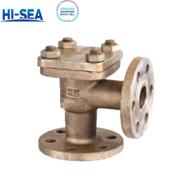
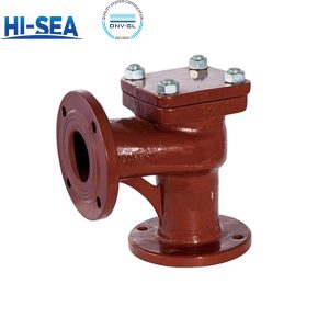
This is a flanged bronze check valve, not a stop check valve or a combined stop-and-non-return valve. It performs one function: the disc opens with forward flow and closes automatically against reverse flow. It has no handwheel and no line-isolation function; isolation for maintenance must be provided by a separate valve. Service media are fresh water, sea water, lubricating oil, fuel oil, air and steam up to 250 °C, at nominal pressures from PN6 to PN25 (0.6–2.5 MPa). The right-angle pattern turns the flow through 90°, so it fits where a straight run is not available—tight pump rooms, manifold headers and branch take-offs. Be clear on what it is not: it is a pure check valve, not a stop check valve, not a regulating or throttling valve, and not a safety or relief device.
Body, bonnet and disc are available in two bronzes, and the choice is a cost-of-ownership decision, not simply a price decision. Cast tin bronze ZCuSn5Pb5Zn5 (code Q1) is the cost-effective default for fresh water, lube oil, fuel oil and low-pressure sea water where downtime is cheap and replacement is planned. Cast nickel-aluminium bronze ZCuAl9Fe4Ni4Mn2 (code Q2) is the standard’s recommended grade for sea water; it carries a higher initial material cost and buys significantly longer service life in moving, aerated or sandy sea water, which matters on main cooling and ballast duty where a shutdown costs far more than the valve. Q2 parts weigh about 8% less than the Q1 figures published here, so the two are not directly comparable on a pure cost-per-kilo basis. This check-valve design has no stem or handwheel, so no stem material grade should be listed. Gaskets and packing shall be non-asbestos materials conforming to CB/T 3589—1994; PTFE components, where used, shall conform to QB/T 4041—2010.
The valve is built and accepted to GB/T 589—2026, with strength, tightness, wall thickness, tolerances, assembly and appearance tied back to GB/T 600—2023. Every valve, not a sample, goes through strength and seat-tightness testing before it leaves; heat treatment, where required, applies to castings only. Each heat of castings carries three test bars stamped with the heat number and kept on file for at least three years, so any valve on your ship can be traced back to its melt. Cast weight is held to the theoretical figures with a positive deviation of no more than 4%.
Quick Selection Guide
B or BS: which flange system?
B (CB/T 4196—2011 flanging) — Best suited for Chinese-built hulls and shipyard piping packages already drilled to the marine flange standard. Widest bore coverage at PN10: DN65 to DN250.
BS (GB/T 9124.1—2019 flanging) — Recommended when the line is specified to PN-series flange dimensions, and for the small end: from DN15 at PN6 and PN25. Covers DN65–DN150 at PN16.
Both are the same 90° hydraulic body; only the flange drilling changes. Do not mix the two codes on one purchase order.
Q1 tin bronze or Q2 nickel-aluminium bronze?
For general service (Q1): fresh water, lube oil, fuel oil, air, and low-duty seawater. Lower initial material cost, entirely adequate where the medium is clean and velocities are moderate.
For critical systems (Q2): main seawater cooling, ballast and fire lines, sand-laden or high-velocity seawater. Higher initial material cost, but delivers significantly longer service life and reduces long-term maintenance and dry-docking risk.
Basic Sructure Of Marine Bronze Flanged Check Valve — B/BSType
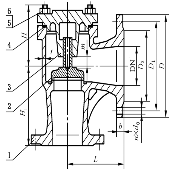
Basic Parameters of Check Valves — Type B & BS (PN / Max. Working Pressure MPa / DN)
| TYPE |
FLANGE STANDARD |
PN |
MAX. WORKING PRESSURE (MPa) |
DN RANGE |
| B |
CB/T 4196-2011 |
10 |
1.0 |
65 – 250 |
| B |
CB/T 4196-2011 |
16 |
1.6 |
125, 150 |
| B |
CB/T 4196-2011 |
25 |
2.5 |
20 – 100 |
| BS |
GB/T 9124.1-2019 |
6 |
0.6 |
15 – 150 |
| BS |
GB/T 9124.1-2019 |
16 |
1.6 |
65 – 150 |
| BS |
GB/T 9124.1-2019 |
25 |
2.5 |
15 – 100 |
Sizes outside the listed ranges are not covered by this standard. Type B (CB/T 4196-2011) and Type BS (GB/T 9124.1-2019) share the same body pattern; only the flange drilling differs, so they are not interchangeable on the same mating flange.
Basic Dimensions of Check Valves — Type B (Structure Dimensions & Mass, Unit: mm / kg)
| PN |
DN |
L (mm) |
H≈ (mm) |
H1 (mm) |
WALL t (mm) |
DISC LIFT m (mm) |
MASS (kg) |
| 10 |
65 |
115 |
94 |
115 |
6 |
19 |
11.3 |
| 10 |
80 |
125 |
104 |
125 |
6 |
23 |
14.3 |
| 10 |
100 |
150 |
117 |
135 |
6 |
28 |
22.7 |
| 10 |
125 |
175 |
129 |
155 |
7 |
35 |
30.4 |
| 10 |
150 |
225 |
163 |
225 |
7 |
38 |
43.0 |
| 10 |
200 |
275 |
224 |
275 |
8 |
59 |
83.0 |
| 10 |
250 |
325 |
245 |
325 |
9 |
65 |
115.0 |
| 16 |
125 |
175 |
143 |
155 |
7 |
35 |
40.0 |
| 16 |
150 |
225 |
163 |
225 |
8 |
38 |
61.5 |
| 25 |
20 |
75 |
67 |
75 |
5 |
6 |
4.1 |
| 25 |
25 |
80 |
66 |
80 |
5 |
7 |
4.6 |
| 25 |
32 |
85 |
68 |
85 |
5 |
9 |
5.3 |
| 25 |
40 |
90 |
76 |
90 |
5 |
12 |
6.6 |
| 25 |
50 |
95 |
85 |
95 |
6 |
15 |
8.3 |
| 25 |
65 |
115 |
94 |
115 |
7 |
19 |
12.7 |
| 25 |
80 |
125 |
110 |
125 |
8 |
23 |
19.0 |
| 25 |
100 |
150 |
108 |
135 |
8 |
28 |
28.3 |
L = centre-to-face dimension (90° body). H≈ = approximate overall height. H1 = centre-to-face dimension of the second port. Mass figures are for cast tin bronze Q1; when nickel-aluminium bronze Q2 is selected, mass is approximately 8 % lower — because of this difference the two are not directly comparable on a pure cost-per-kilo basis.
Flange Connection & Bolting of Check Valves — Type B (CB/T 4196-2011, Unit: mm)
| PN |
DN |
D |
D1 |
D2 |
d0 |
b |
n (PCS) |
BOLT TH. |
| 10 |
65 |
155 |
123 |
104 |
15 |
14 |
6 |
M14 |
| 10 |
80 |
170 |
138 |
118 |
15 |
14 |
8 |
M14 |
| 10 |
100 |
190 |
158 |
138 |
15 |
14 |
8 |
M14 |
| 10 |
125 |
215 |
183 |
164 |
15 |
14 |
10 |
M14 |
| 10 |
150 |
240 |
208 |
190 |
15 |
14 |
12 |
M14 |
| 10 |
200 |
310 |
273 |
250 |
17 |
17 |
12 |
M16 |
| 10 |
250 |
380 |
336 |
310 |
21 |
21 |
14 |
M20 |
| 16 |
125 |
225 |
187 |
168 |
17 |
17 |
10 |
M16 |
| 16 |
150 |
255 |
217 |
196 |
19 |
19 |
12 |
M16 |
| 25 |
20 |
95 |
68 |
48 |
13 |
12 |
4 |
M12 |
| 25 |
25 |
105 |
73 |
56 |
13 |
13 |
4 |
M12 |
| 25 |
32 |
115 |
83 |
64 |
15 |
13 |
6 |
M14 |
| 25 |
40 |
125 |
93 |
74 |
15 |
14 |
6 |
M14 |
| 25 |
50 |
135 |
103 |
84 |
15 |
14 |
6 |
M14 |
| 25 |
65 |
170 |
132 |
110 |
17 |
17 |
8 |
M16 |
| 25 |
80 |
185 |
147 |
126 |
17 |
19 |
8 |
M16 |
| 25 |
100 |
205 |
167 |
146 |
17 |
19 |
10 |
M16 |
D = flange OD, D1 = bolt circle, D2 = sealing face diameter, d0 = bolt hole, b = flange thickness, n = number of bolt holes, Th. = bolt thread. Studs and nuts are stainless steel A4-70 / A4-50 per GB/T 3098.6-2023 and GB/T 3098.15-2023; bolts are not supplied unless ordered separately.
Basic Dimensions of Check Valves — Type BS PN6 (Structure Dimensions & Mass, Unit: mm / kg)
| DN |
L (mm) |
H≈ (mm) |
WALL t (mm) |
DISC LIFT m (mm) |
MASS (kg) |
| 15 |
90 |
70 |
4 |
7 |
3.6 |
| 20 |
95 |
70 |
4 |
7 |
4.0 |
| 25 |
100 |
70 |
4 |
7 |
4.4 |
| 32 |
105 |
70 |
5 |
9 |
6.0 |
| 40 |
115 |
77 |
5 |
12 |
7.5 |
| 50 |
125 |
80 |
5 |
15 |
10.1 |
| 65 |
145 |
89 |
6 |
19 |
13.4 |
| 80 |
155 |
112 |
6 |
23 |
18.5 |
| 100 |
175 |
113 |
7 |
28 |
25.0 |
| 125 |
200 |
123 |
7 |
35 |
33.5 |
| 150 |
225 |
163 |
7 |
38 |
42.5 |
L = centre-to-face dimension. H≈ = approximate overall height. Mass is for cast tin bronze Q1; nickel-aluminium bronze Q2 is approximately 8 % lighter — the two are not directly comparable on a pure cost-per-kilo basis.
Flange Connection & Bolting of Check Valves — Type BS PN6 (GB/T 9124.1-2019, Unit: mm)
| DN |
D |
D1 |
D2 |
d0 |
b |
n (PCS) |
BOLT TH. |
| 15 |
80 |
55 |
40 |
11 |
12 |
4 |
M10 |
| 20 |
90 |
65 |
50 |
11 |
12 |
4 |
M10 |
| 25 |
100 |
75 |
60 |
11 |
14 |
4 |
M10 |
| 32 |
120 |
90 |
70 |
14 |
15 |
4 |
M12 |
| 40 |
130 |
100 |
80 |
14 |
16 |
4 |
M12 |
| 50 |
140 |
110 |
90 |
14 |
17 |
4 |
M12 |
| 65 |
160 |
130 |
110 |
14 |
17 |
4 |
M12 |
| 80 |
190 |
150 |
128 |
14 |
19 |
4 |
M16 |
| 100 |
210 |
170 |
148 |
14 |
19 |
4 |
M16 |
| 125 |
240 |
200 |
178 |
18 |
20 |
8 |
M16 |
| 150 |
265 |
225 |
202 |
18 |
20 |
8 |
M16 |
Flange drilling to GB/T 9124.1-2019 PN6. Sealing face available as raised face (R) or full face (F) — state this in the designation.
Basic Dimensions of Check Valves — Type BS PN16 (Structure Dimensions & Mass, Unit: mm / kg)
| DN |
L (mm) |
H≈ (mm) |
WALL t (mm) |
DISC LIFT m (mm) |
MASS (kg) |
| 65 |
145 |
97 |
6 |
19 |
15.2 |
| 80 |
155 |
117 |
6 |
23 |
21.9 |
| 100 |
175 |
121 |
7 |
28 |
32.9 |
| 125 |
200 |
129 |
7 |
35 |
39.1 |
| 150 |
225 |
163 |
8 |
38 |
58.0 |
Mass is for cast tin bronze Q1; nickel-aluminium bronze Q2 is approximately 8 % lighter — the two are not directly comparable on a pure cost-per-kilo basis.
Flange Connection & Bolting of Check Valves — Type BS PN16 (GB/T 9124.1-2019, Unit: mm)
| DN |
D |
D1 |
D2 |
d0 |
b |
n (PCS) |
BOLT TH. |
| 65 |
185 |
145 |
122 |
18 |
17 |
4 * |
M16 |
| 80 |
200 |
160 |
138 |
18 |
19 |
8 |
M16 |
| 100 |
220 |
180 |
158 |
18 |
20 |
8 |
M16 |
| 125 |
250 |
210 |
188 |
18 |
22 |
8 |
M16 |
| 150 |
285 |
240 |
212 |
22 |
22 |
8 |
M20 |
* DN65 PN16: bolt-hole coordination applies when the mating flange is to GB/T 9124.1-2019 — confirm the counterpart flange drawing before release. Studs and nuts are A4-70 / A4-50 stainless steel and are not supplied unless ordered separately.
Basic Dimensions of Check Valves — Type BS PN25 (Structure Dimensions & Mass, Unit: mm / kg)
| DN |
L (mm) |
H≈ (mm) |
WALL t (mm) |
DISC LIFT m (mm) |
MASS (kg) |
| 15 |
90 |
70 |
5 |
7 |
4.7 |
| 20 |
95 |
70 |
5 |
7 |
5.1 |
| 25 |
100 |
70 |
5 |
7 |
6.0 |
| 32 |
105 |
70 |
5 |
9 |
7.8 |
| 40 |
115 |
77 |
a5 |
12 |
9.6 |
| 50 |
125 |
81 |
6 |
15 |
11.8 |
| 65 |
145 |
97 |
7 |
19 |
16.2 |
| 80 |
155 |
117 |
7 |
23 |
23.2 |
| 100 |
175 |
121 |
8 |
28 |
35.0 |
Mass is for cast tin bronze Q1; nickel-aluminium bronze Q2 is approximately 8 % lighter — the two are not directly comparable on a pure cost-per-kilo basis.
Flange Connection & Bolting of Check Valves — Type BS PN25 (GB/T 9124.1-2019, Unit: mm)
| DN |
D |
D1 |
D2 |
d0 |
b |
n (PCS) |
BOLT TH. |
| 15 |
95 |
65 |
45 |
14 |
12 |
4 |
M12 |
| 20 |
105 |
75 |
58 |
14 |
12 |
4 |
M12 |
| 25 |
115 |
85 |
68 |
14 |
14 |
4 |
M12 |
| 32 |
140 |
100 |
78 |
18 |
15 |
4 |
M16 |
| 40 |
150 |
110 |
88 |
18 |
16 |
4 |
M16 |
| 50 |
165 |
125 |
102 |
18 |
17 |
4 |
M16 |
| 65 |
185 |
145 |
122 |
18 |
17 |
8 |
M16 |
| 80 |
200 |
160 |
138 |
18 |
19 |
8 |
M16 |
| 100 |
235 |
190 |
162 |
22 |
20 |
8 |
M20 |
Flange drilling to GB/T 9124.1-2019 PN25. Length tolerance for Type BS follows GB/T 11698-2026; for Type BS the structural length is checked with a steel rule, vernier caliper or equivalent-grade instrument.
QA & Testing
Strength (shell test) — requirement GB/T 600-2023 §4.14, method §5.1.1.3. Applied to every valve, not to a sample.
Tightness (seat test) — requirement GB/T 600-2023 §4.15, method §5.1.2.3. Verifies that the disc re-seats and holds on reverse flow.
Wall thickness — GB/T 600-2023 §4.2; thickness tolerance §4.5.1; verified by thickness gauge, caliper or steel rule (§6.3.1).
Dimensional tolerance — GB/T 600-2023 §4.5. Structural length: Type B to the approved construction drawing, Type BS to GB/T 11698-2026 (§5.4.3).
Geometric tolerance — GB/T 600-2023 §4.7; inspected to GB/T 1958.
Assembly — GB/T 600-2023 §4.10; checked visually and with caliper (§6.5).
Appearance — GB/T 600-2023 §4.11; visual (§6.6).
Mass tolerance — finished mass shall not exceed the theoretical figure by more than +4 %; weighed on a scale with a division of ≤0.01 kg (§5.8, §6.7).
Material traceability — each casting heat retains at least 3 numbered test bars, kept for not less than 3 years (§5.1.2). Material certificate issued on request.
Inspection regime — type test on 3 samples with doubling on failure (§7.2); factory test on each individual valve (§7.3.2); rework and re-test permitted on a single failure (§7.3.3).
Marking — to GB/T 3032 (§5.9). Packing and storage — GB/T 600-2023 §6.3 and §6.4.
FAQ
Q1. Angle body or straight body — what does the 90° actually cost me?
An angle body removes one elbow and shortens the pipe run, which is real space and welding saved. The trade-off is honest: the flow turns 90° through the body, so pressure drop is higher than a straight-pattern check valve of the same size. Best suited for corners in auxiliary systems and where installation space drives the layout. If the line is on a tight Δp budget — long suction runs, gravity-fed systems — specify a straight-pattern valve instead.
Q2.Can I use this as a shut-off valve, or to regulate flow?
No. This is a check valve: it opens and closes only in response to flow direction and has no operator, no stem and no position indication. It gives no positive isolation and no throttling capability. If you need to isolate a line for maintenance, a stop valve or a stop-check valve is required — this valve sits alongside it, not in place of it.
Q3.Why are there two versions, B and BS — will they interchange?
They share the same body pattern but not the same flange. Type B is drilled to CB/T 4196-2011; Type BS to GB/T 9124.1-2019. The bolt circle, hole count and sealing face diameter differ, so one will not bolt onto the other’s mating flange. Check your piping spec or the mating flange drawing before ordering — this is the single most common ordering error on this product.