Overview
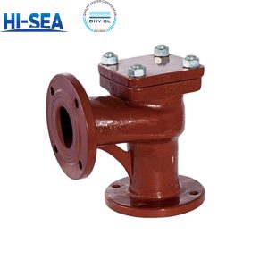
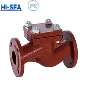
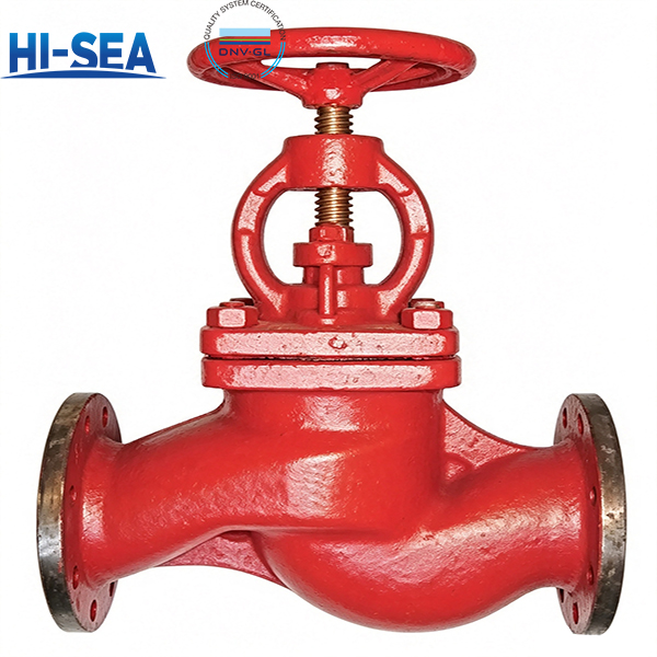
A/AS-type flanged stop-check valves combine manual isolation and automatic non-return in one cast-iron body for ship piping. They serve sea water, fresh water, lube oil and fuel oil lines. The straight-through layout suits inline runs where reverse flow must be arrested without a separate check valve.
Choose the gray-iron body for fresh water, lube oil and budget-driven general services — the cost-effective default. Ductile iron adds margin for critical seawater circuits where downtime outweighs material cost, giving longer service life. For fuel oil, specify flexible graphite packing and gasket; PTFE is the standard alternative.
GB/T 591-2026 governs design, testing and marking. Strength and tightness follow GB/T 600-2023, with dimensional and geometrical tolerances controlled to the same document; AS-type face-to-face lengths follow GB/T 11698-2026. Every heat keeps three retained test bars for three years, and positive mass tolerance is capped at 4%.
Quick Selection Guide
Flange standard — A vs AS (both straight-through)
A type — flanges to CB/T 4196-2011. Best suited for retrofit, domestic-built tonnage and legacy spares matching an existing bolt pattern.
AS type — flanges to GB/T 9124.1-2019 (PN series). Recommended when new-build or international shipyard flange coordination is required.
Body material — HT vs QT
HT200 grey iron — cost-effective default. Best suited for fresh water, lube oil and general low-load lines.
QT400-18 ductile iron — higher initial material cost, longer service life. Recommended when handling raw sea water, or when maintenance and downtime costs far exceed the valve’s initial cost.
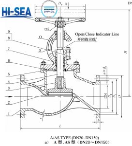
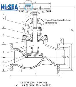
| TYPE | FLANGE STANDARD | PN | MAXWORKINGPRESSUE | DN (mm) | MEDIUM |
|---|---|---|---|---|---|
| A | CB/T 4196—2011 | 10 | 1.0 | 65–150 | Sea water, fresh water, lube oil, fuel oil |
| A | CB/T 4196—2011 | 16 | 1.6 | 20–50 | Sea water, fresh water, lube oil, fuel oil |
| AS | GB/T 9124.1—2019 | 6 | 0.6 | 50–300 | Sea water, fresh water, lube oil, fuel oil |
| AS | GB/T 9124.1—2019 | 10 | 1.0 | 65–250 | Sea water, fresh water, lube oil, fuel oil |
| AS | GB/T 9124.1—2019 | 16 | 1.6 | 20–50 | Sea water, fresh water, lube oil, fuel oil |
A and AS are both straight-through types; they differ only in flange standard. Both ratings and DN ranges are shown as specified in the standard.
Basic Dimensions — Type A, PN10 (mm / kg)
| DN | L | H≈ | t | D | D1 | D2 | d0 | b | n | Th | D0 | S | m | WT (kg) |
|---|---|---|---|---|---|---|---|---|---|---|---|---|---|---|
| 65 | 290 | 308 | 9 | 155 | 123 | 104 | 15 | 15 | 6 | M14 | 140 | 12 | 17 | 18.4 |
| 80 | 310 | 339 | 9 | 170 | 138 | 118 | 15 | 15 | 8 | M14 | 160 | 14 | 20 | 22.6 |
| 100 | 350 | 364 | 10 | 190 | 158 | 138 | 15 | 15 | 8 | M14 | 180 | 14 | 25 | 30.7 |
| 125 | 400 | 414 | 10 | 215 | 183 | 164 | 15 | 15 | 10 | M14 | 200 | 17 | 32 | 38.9 |
| 150 | 480 | 468 | 11 | 240 | 208 | 190 | 15 | 16 | 12 | M14 | 200 | 17 | 38 | 54.6 |
Type A columns. H ≈ is the centre-to-handwheel open height; m is disc lift. Flange dimensions follow CB/T 4196—2011.
| DN | L | H≈ | t | D | D1 | D2 | d0 | b | n | Th | D0 | S | m | WT (kg) |
|---|---|---|---|---|---|---|---|---|---|---|---|---|---|---|
| 20 | 150 | 217 | 7 | 95 | 68 | 48 | 13 | 14 | 4 | M12 | 80 | 8 | 7 | 5.6 |
| 25 | 160 | 217 | 7 | 105 | 73 | 56 | 13 | 14 | 4 | M12 | 80 | 8 | 7 | 5.7 |
| 32 | 180 | 236 | 7 | 115 | 83 | 64 | 15 | 15 | 6 | M14 | 100 | 9 | 9 | 6.8 |
| 40 | 200 | 260 | 8 | 125 | 93 | 74 | 15 | 16 | 6 | M14 | 120 | 11 | 11 | 9.0 |
| 50 | 230 | 288 | 8 | 135 | 103 | 84 | 15 | 16 | 6 | M14 | 140 | 12 | 14 | 11.8 |
Type A columns. Flange dimensions follow CB/T 4196—2011. Theoretical weight shown; permitted positive deviation 4% per clause 5.8.
| DN | L | H≈ | t | D | D1 | D2 | d0 | b | n | Th | D0 | S | m | WT (kg) |
|---|---|---|---|---|---|---|---|---|---|---|---|---|---|---|
| 50 | 230 | 288 | 8 | 140 | 110 | 90 | 14 | 16 | 4 | M12 | 140 | 12 | 14 | 12.1 |
| 65 | 290 | 308 | 9 | 160 | 130 | 110 | 14 | 16 | 4 | M12 | 160 | 14 | 17 | 18.7 |
| 80 | 310 | 339 | 9 | 190 | 150 | 128 | 18 | 18 | 8 | M16 | 160 | 14 | 20 | 23.4 |
| 100 | 350 | 364 | 10 | 210 | 170 | 148 | 18 | 18 | 8 | M16 | 180 | 14 | 25 | 34.2 |
| 125 | 400 | 414 | 10 | 240 | 200 | 178 | 18 | 20 | 8 | M16 | 200 | 17 | 32 | 42.1 |
| 150 | 480 | 465 | 11 | 265 | 225 | 202 | 18 | 20 | 8 | M16 | 200 | 17 | 38 | 57.8 |
| 175 | 540 | 541 | 11 | 295 | 255 | 232 | 18 | 22 | 12 | M16 | 280 | 24 | 42 | 75.9 |
| 200 | 600 | 596 | 11 | 320 | 280 | 258 | 18 | 22 | 12 | M16 | 280 | 24 | 50 | 101.0 |
| 250 | 730 | 688 | 13 | 375 | 335 | 312 | 18 | 24 | 12 | M16 | 360 | 27 | 65 | 156.0 |
| 300 | 850 | 774 | 13 | 440 | 395 | 365 | 22 | 24 | 12 | M20 | 450 | 32 | 75 | 219.0 |
Type AS columns. Flange dimensions follow GB/T 9124.1—2019. When ordering to this flange, check bolt-hole alignment (standard note a). d0 values follow bolt size: M12→14, M16→18, M20→22.
| DN | L | H≈ | t | D | D1 | D2 | d0 | b | n | Th | D0 | S | m | WT (kg) |
|---|---|---|---|---|---|---|---|---|---|---|---|---|---|---|
| 65 | 290 | 308 | 9 | 185 | 145 | 122 | 18 | 20 | 4 | M16 | 140 | 12 | 17 | 21.1 |
| 80 | 310 | 339 | 9 | 200 | 160 | 138 | 18 | 22 | 8 | M16 | 160 | 14 | 20 | 25.6 |
| 100 | 350 | 364 | 10 | 220 | 180 | 158 | 18 | 24 | 8 | M16 | 180 | 14 | 25 | 34.7 |
| 125 | 400 | 414 | 10 | 250 | 210 | 188 | 18 | 26 | 8 | M16 | 200 | 17 | 32 | 43.9 |
| 150 | 480 | 468 | 11 | 285 | 240 | 212 | 22 | 26 | 8 | M20 | 200 | 17 | 38 | 61.8 |
| 175 | 540 | 541 | 11 | 315 | 270 | 242 | 22 | 28 | 8 | M20 | 280 | 24 | 42 | 79.4 |
| 200 | 600 | 603 | 11 | 340 | 295 | 268 | 22 | 28 | 8 | M20 | 360 | 27 | 50 | 105.0 |
| 250 | 730 | 706 | 13 | 395 | 350 | 320 | 22 | 28 | 12 | M20 | 450 | 32 | 65 | 158.0 |
Type AS columns. Flange dimensions follow GB/T 9124.1—2019. DN65 bolt count per standard note a — confirm bolt-hole coordination when matching this flange.
| DN | L | H≈ | t | D | D1 | D2 | d0 | b | n | Th | D0 | S | m | WT (kg) |
|---|---|---|---|---|---|---|---|---|---|---|---|---|---|---|
| 20 | 150 | 217 | 7 | 105 | 75 | 58 | 14 | 16 | 4 | M12 | 80 | 8 | 7 | 6.2 |
| 25 | 160 | 217 | 7 | 115 | 85 | 68 | 14 | 16 | 4 | M12 | 80 | 8 | 7 | 6.6 |
| 32 | 180 | 236 | 7 | 140 | 100 | 78 | 18 | 18 | 4 | M16 | 100 | 9 | 9 | 8.4 |
| 40 | 200 | 260 | 8 | 150 | 110 | 88 | 18 | 18 | 4 | M16 | 120 | 11 | 11 | 10.8 |
| 50 | 230 | 288 | 8 | 165 | 125 | 102 | 18 | 20 | 4 | M16 | 140 | 12 | 14 | 14.1 |
Type AS columns. Flange dimensions follow GB/T 9124.1—2019. Structure length tolerance follows GB/T 11698—2026.
| PART | MATERIAL | GRADE | STANDARD |
|---|---|---|---|
| Body / Bonnet | Grey cast iron | HT200 | GB/T 9439—2023 |
| Body / Bonnet | Ductile iron | QT400-18 | GB/T 1348—2019 |
| Disc | Cast tin bronze | ZCuSn10Zn2 | GB/T 1176—2013 |
| Stem | Aluminium bronze | QAl9—2 | GB/T 4423—2020 |
| Seat | Cast aluminium bronze | ZCuAl9Mn2 | GB/T 1176—2013 |
| Packing | PTFE braided / flexible graphite | F4SD / RSM | JB/T 6626—2011 / CB/T 3589—1994 |
| Gasket | PTFE / flexible graphite | PTFE / RSM | QB/T 4041—2010 / CB/T 3589—1994 |
| Stud | Class 6.8 | — | GB/T 898—1988 |
| Nut | Class 6 | — | GB/T 6170—2015 |
| Handwheel | Cast steel / ductile iron | ZG230-450 / QT400-15 | CB/T 3530—1993 |
QA & Testing
Core Performance
Strength — Per GB/T 600—2023 §4.14, tested to §5.1.1.2. A mandatory item on both type and factory inspection (Table 5).
Tightness — Seat and body tightness per GB/T 600—2023 §4.15, tested to §5.1.2.2. Checked on every unit before release.
Dimensional & Geometric Control
Wall Thickness — Per GB/T 600—2023 §4.2, tolerance to §4.5.1; verified by thickness gauge, caliper or steel rule (§6.3.1).
Linear Dimensions — Tolerances per GB/T 600—2023 §4.5, measured with matching-grade gauges (§6.3.2). Type-test item only.
Face-to-Face (L) — Type A to the approved drawing; Type AS to GB/T 11698—2026. Verified by steel rule or vernier caliper (§6.3.3).
Geometric Tolerance — Per GB/T 600—2023 §4.7, inspected to GB/T 1958. Controlled at type-test stage (Table 5).
Weight — Theoretical per Tables 2–3, positive deviation ≤ 4% (§5.8); weighed on a scale of 0.01 kg resolution or finer (§6.7).
Assembly & Appearance — Per GB/T 600—2023 §4.10 and §4.11; visual or caliper check (§6.5, §6.6). Both are 100% factory items.
Material Traceability
Heat Traceability — Minimum three numbered test bars per heat, retained for ≥ 3 years (§5.1.2). Chemistry and mechanical properties are accepted by heat lot before production release (§7.3.2).
Body & Trim — HT200 grey iron (GB/T 9439—2023) or QT400-18 ductile iron (GB/T 1348—2019); bronze disc, seat and stem per GB/T 1176—2013 and GB/T 4423—2020. All material is inspected before machining (§5.1.1).
Media-Driven Selection — Fuel oil service requires flexible graphite packing and gasket (§5.1.1). Anti-de-alloying treatment for aluminium bronze is available on request in sea water duty.
Inspection & Delivery
Type Test — Three samples (§7.2.3), full scope per Table 5. Any failure triggers double-quantity re-sampling; a second failure rejects the lot (§7.2.4).
Factory Test — Per Table 5: strength, tightness, assembly, appearance and marking on every valve; weight by agreement (§7.3.1). Chemistry and mechanical checks are by heat lot, all others piece-by-piece (§7.3.2).
Marking — Per GB/T 3032 (§5.9), verified visually (§6.8).
Packing & Storage — Per GB/T 600—2023 §6.3 and §6.4 (clause 8).