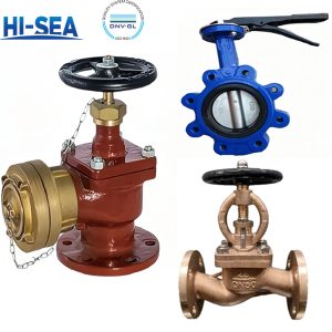
Overview
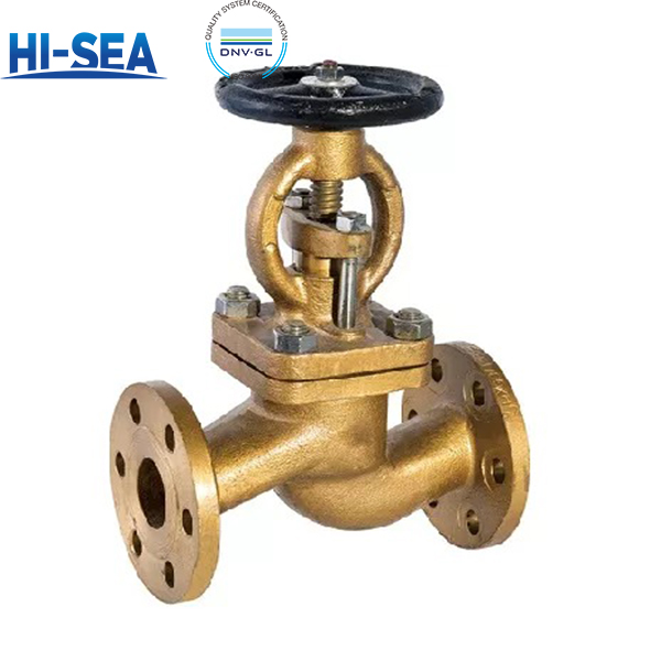
The A/AS series are straight-through, handwheel-operated marine bronze flanged stop valves intended for isolation service in shipboard piping systems handling fresh water, seawater, lube oil, fuel oil, air, and steam up to 250 °C. A-type valves use flange connection dimensions and sealing faces according to CB/T 4196—2011; AS-type valves use GB/T 9124.1—2019. Across the A/AS range, PN6/PN10/PN16/PN25 and DN15–DN250 are covered depending on type; exact size/pressure combinations are listed in the specification tables.
The valves use a bronze body, bonnet, disc and packing nut, an aluminium bronze stem, PTFE braided or flexible graphite packing, PTFE or flexible graphite gasket, stainless steel studs/nuts, and a CF8 handwheel with open/close indication. For seawater service, nickel-aluminium bronze is recommended; for fuel oil and steam, flexible graphite packing and gasket should be selected. The standard also notes the de-alloying corrosion risk of aluminium bronze in seawater, and anti-de-alloying treatment can be provided on request.
The product standard is GB/T 587—2026. Its strength and tightness requirements are specified by reference to GB/T 600—2023, General Specifications for Marine Piping Valves and Fittings, which serves as the general technical basis for marine valve testing. AS-type structural length tolerance follows GB/T 11698—2026; A-type follows the construction drawing. Theoretical weight is based on cast tin bronze, with positive deviation not exceeding 4%; nickel-aluminium bronze is 8% lighter. Castings require at least three heat-numbered test bars per heat, retained for not less than 3 years. Type inspection uses three samples; factory inspection, marking, packaging and storage follow the above standards. Specific clause references and test pressure values are listed in the Compliance & Testing section below.
Choose the Right Version for Your Piping System
A Type: Flange dimensions per CB/T 4196—2011. (Traditional marine standard)
AS Type: Flange dimensions per GB/T 9124.1—2019. (For coordination with GB standard flanges)
Q1 Material-Cast Tin Bronze (ZCuSn5Pb5Zn5/C83600)
The standard, cost eftective choice for general marine serice Q1 ofters a wel-balanced combination of moderate stength. good castablity. excelentmachinability, and reliabl resistance to fresh water, seawater. lube oil. fuel oil, air, and steam. It is best suited for low pressure. moderate temperature.and low- velocity piping condtions where the medium is non -aggressive and the valve is not subjected to high mechanical loads or severe erosion Forseaater lines operating at low pressure and ambient temperature. Q1 remains a proven and economical solution. Long term service temperature should not exceed 250°C.
Q2 Material – Nickel-Aluminium Bronze (ZCuA19Fe4Ni4Mn2 / C95800)
The upgraded, hgh performance choice for demanding seawater and high pressure service. Q2 ofters significantly higher mechanical strength superioteroson corosion resistance in Rowing seawater, and a weiht reduction of approximately S% compared to O1 Iis best suted for high pressure, hghfow-rate, sand laden, or critical seawater piping conditions where tin bronze would face severe erosion risks or mechanical overload For critical rawseawater lines, O2 is the recommended material by the standard, and anti-de-alloving treatment can be provided on request.
| Type and application scope of Type A / AS stop valves(GB/T 587—2026) | |||||
|---|---|---|---|---|---|
| Type | Body design | Flange dimensions & sealing face | Face-to-face tolerance | Service media and temperature | Mating flange |
| A | Straight-through (globe type) | CB/T 4196—2011 | As specified on the construction drawing |
Fresh water, sea water, lube oil, fuel oil, air and steam up to 250 °C |
CB-series marine flanges |
| AS | Straight-through (globe type) | GB/T 9124.1—2019 (PN series) | GB/T 11698—2026 | GB-series steel pipe flanges | |
| Types B / BS are the angle-pattern versions of the same two flange systems and are not covered here. Strength and tightness per GB/T 600—2023, 4.14 and 4.15; wall thickness 4.2; dimensional tolerances 4.5; geometrical tolerances 4.7. | |||||
| Basic parameters, Type A / AS(GB/T 587—2026) | ||||
|---|---|---|---|---|
| Type | PN | Max. working pressure (MPa) | Size range (DN) | Service media |
|
A |
10 | 1.0 | 65 – 250 |
Fresh water, sea water, lube oil, fuel oil, air; steam up to 250 °C |
| 16 | 1.6 | 125, 150 | ||
| 25 | 2.5 | 20 – 125 | ||
|
AS |
6 | 0.6 | 15 – 150 | |
| 16 | 1.6 | 65 – 150 | ||
| 25 | 2.5 | 15 – 125 | ||
| Type A has no PN6 rating; Type AS has no PN10 rating. DN200 and DN250 at PN10 are new in this edition. Body material: Q1 cast tin bronze, Q2 nickel-aluminium bronze. | ||||
| Basic dimensions, Type A — CB/T 4196—2011 flanges(GB/T 587—2026) | |||||||||||||
|---|---|---|---|---|---|---|---|---|---|---|---|---|---|
| PN | DN | L | H≈ | t | D | D1 | D2 | d0 | b | n | Thread | Lift | Weight (kg) |
|
10 |
65 | 290 | 310 | 6 | 155 | 123 | 104 | 15 | 14 | 6 | M14 | 19 | 16.4 |
| 80 | 310 | 345 | 6 | 170 | 138 | 118 | 15 | 14 | 8 | M14 | 26 | 20.6 | |
| 100 | 350 | 374 | 6 | 190 | 158 | 138 | 15 | 14 | 8 | M14 | 35 | 31.6 | |
| 125 | 400 | 426 | 7 | 215 | 183 | 164 | 15 | 14 | 10 | M14 | 44 | 40.0 | |
| 150 | 480 | 487 | 7 | 240 | 208 | 190 | 15 | 14 | 12 | M14 | 57 | 59.5 | |
| 200 | 600 | 586 | 8 | 310 | 273 | 250 | 17 | 17 | 12 | M16 | 59 | 137.0 | |
| 250 | 730 | 753 | 9 | 380 | 336 | 310 | 21 | 21 | 14 | M20 | 65 | 216.0 | |
| 16 | 125 | 400 | 465 | 7 | 225 | 187 | 168 | 17 | 19 | 10 | M16 | 44 | 56.6 |
| 150 | 480 | 524 | 8 | 255 | 217 | 196 | 17 | 19 | 12 | M16 | 57 | 66.4 | |
|
25 |
20 | 150 | 217 | 5 | 95 | 68 | 48 | 13 | 11 | 4 | M12 | 7 | 5.4 |
| 25 | 160 | 217 | 5 | 105 | 73 | 56 | 13 | 12 | 4 | M12 | 7 | 6.1 | |
| 32 | 180 | 236 | 5 | 115 | 83 | 64 | 15 | 13 | 6 | M14 | 9 | 7.2 | |
| 40 | 200 | 260 | 5 | 125 | 93 | 74 | 15 | 13 | 6 | M14 | 11 | 9.7 | |
| 50 | 230 | 288 | 6 | 135 | 103 | 84 | 15 | 13 | 6 | M14 | 14 | 12.3 | |
| 65 | 290 | 335 | 7 | 170 | 132 | 110 | 17 | 15 | 8 | M16 | 18 | 20.5 | |
| 80 | 310 | 366 | 7 | 185 | 147 | 126 | 17 | 16 | 8 | M16 | 24 | 27.4 | |
| 100 | 350 | 427 | 8 | 205 | 167 | 146 | 17 | 16 | 10 | M20 | 35 | 42.0 | |
| 125 | 400 | 493 | 9 | 240 | 196 | 172 | 21 | 19 | 10 | M20 | 44 | 66.6 | |
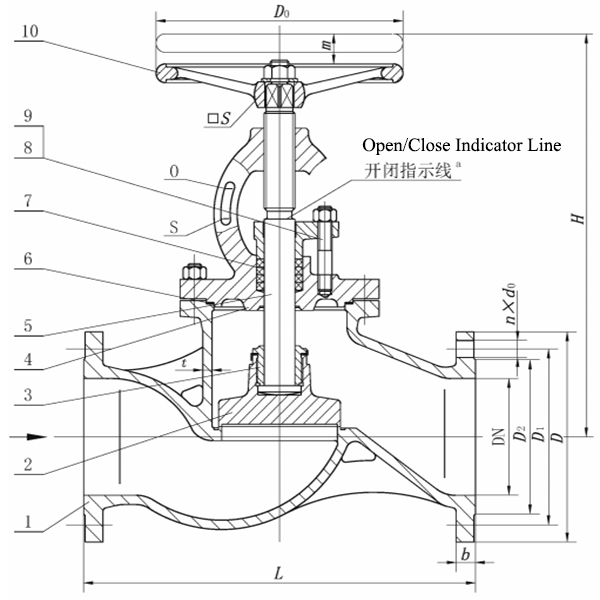
| Dimensions in mm; weight in kg. L face-to-face length · H≈ centre-to-handwheel height, valve open · t wall thickness · D flange OD · D1 bolt circle dia. · D2 raised face dia. · d0 bolt hole dia. · b flange thickness · n number of bolts · Lift mm. Weights are based on cast tin bronze; deduct 8 % for nickel-aluminium bronze. Positive weight deviation shall not exceed 4 % of the theoretical value. | |||||||||||||
| Basic dimensions, Type AS — GB/T 9124.1—2019 PN flanges(GB/T 587—2026) | |||||||||||||
|---|---|---|---|---|---|---|---|---|---|---|---|---|---|
| PN | DN | L | H≈ | t | D | D1 | D2 | d0 | b | n | Thread | Lift | Weight (kg) |
|
6 |
15 | 130 | 217 | 4 | 80 | 55 | 40 | 11 | 12 | 4 | M10 | 7 | 4.8 |
| 20 | 150 | 217 | 4 | 90 | 65 | 50 | 11 | 12 | 4 | M10 | 7 | 5.6 | |
| 25 | 160 | 217 | 4 | 100 | 75 | 60 | 11 | 14 | 4 | M10 | 7 | 6.3 | |
| 32 | 180 | 236 | 5 | 120 | 90 | 70 | 14 | 15 | 4 | M12 | 9 | 7.5 | |
| 40 | 200 | 260 | 5 | 130 | 100 | 80 | 14 | 16 | 4 | M12 | 11 | 9.6 | |
| 50 | 230 | 288 | 5 | 140 | 110 | 90 | 14 | 17 | 4 | M12 | 14 | 13.2 | |
| 65 | 290 | 310 | 6 | 160 | 130 | 110 | 14 | 17 | 4 | M12 | 19 | 18.9 | |
| 80 | 310 | 345 | 6 | 190 | 150 | 128 | 18 | 19 | 4 | M16 | 26 | 24.9 | |
| 100 | 350 | 374 | 6 | 210 | 170 | 148 | 18 | 20 | 4 | M16 | 35 | 37.1 | |
| 125 | 400 | 426 | 7 | 240 | 200 | 178 | 18 | 20 | 8 | M16 | 44 | 50.0 | |
| 150 | 480 | 487 | 7 | 265 | 225 | 202 | 18 | 20 | 8 | M16 | 57 | 74.7 | |
|
16 |
65 | 290 | 335 | 6 | 185 | 145 | 122 | 18 | 17 | 4a | M16 | 18 | 22.9 |
| 80 | 310 | 366 | 6 | 200 | 160 | 138 | 18 | 19 | 8 | M16 | 24 | 31.7 | |
| 100 | 350 | 427 | 6 | 220 | 180 | 158 | 18 | 20 | 8 | M16 | 35 | 48.1 | |
| 125 | 400 | 465 | 7 | 250 | 210 | 188 | 18 | 22 | 8 | M16 | 44 | 57.6 | |
| 150 | 480 | 524 | 8 | 285 | 240 | 212 | 22 | 22 | 8 | M20 | 57 | 76.5 | |
|
25 |
15 | 130 | 217 | 5 | 95 | 65 | 45 | 14 | 12 | 4 | M12 | 7 | 5.7 |
| 20 | 150 | 217 | 5 | 105 | 75 | 58 | 14 | 12 | 4 | M12 | 7 | 6.2 | |
| 25 | 160 | 217 | 5 | 115 | 85 | 68 | 14 | 14 | 4 | M12 | 7 | 6.8 | |
| 32 | 180 | 236 | 5 | 140 | 100 | 78 | 18 | 15 | 4 | M16 | 9 | 9.3 | |
| 40 | 200 | 260 | 5 | 150 | 110 | 88 | 18 | 16 | 4 | M16 | 11 | 11.4 | |
| 50 | 230 | 288 | 6 | 165 | 125 | 102 | 18 | 17 | 4 | M16 | 14 | 16.2 | |
| 65 | 290 | 335 | 7 | 185 | 145 | 122 | 18 | 17 | 8 | M16 | 19 | 23.1 | |
| 80 | 310 | 366 | 7 | 200 | 160 | 138 | 18 | 19 | 8 | M16 | 24 | 31.9 | |
| 100 | 350 | 427 | 8 | 235 | 190 | 162 | 22 | 20 | 8 | M20 | 35 | 51.0 | |
| 125 | 400 | 493 | 9 | 270 | 220 | 188 | 26 | 26 | 8 | M24 | 44 | 80.0 | |
| Dimensions in mm; weight in kg. a Bolt hole alignment to be checked when GB/T 9124.1—2019 flanges are used. The standard prints 113 for b at PN25 DN32–DN50, taken here as 13 (typo in the original). Weights based on cast tin bronze; deduct 8 % for nickel-aluminium bronze. Symbol legend: see Table 4. | |||||||||||||
| Materials of principal parts(GB/T 587—2026, Table 4) | ||||
|---|---|---|---|---|
| Part | Material | Grade | Standard | Selection note |
| Body, bonnet, disc, gland nut | Cast tin bronze | ZCuSn5Pb5Zn5 | GB/T 1176—2013 | Standard choice for fresh water, lube oil and air |
| Nickel-aluminium bronze | ZCuAl9Fe4Ni4Mn2 | Preferred for sea water service | ||
| Stem | Aluminium bronze (drawn bar) | QAl9-2 | GB/T 4423—2020 | De-alloying corrosion risk in sea water; resistant treatment available on request |
| Packing | PTFE braided packing | F4SD | JB/T 6626—2011 | General media |
| Flexible graphite | RSM | CB/T 3589—1994 | Fuel oil and steam service | |
| Gasket | PTFE | PTFE | QB/T 4041—2010 | General media |
| Flexible graphite | RSM | CB/T 3589—1994 | Fuel oil and steam service | |
| Stud bolt | Stainless steel | A4-70 | GB/T 3098.6—2023 | — |
| Nut | Stainless steel | A4-50 | GB/T 3098.15—2023 | — |
| Handwheel | Stainless steel | CF8 | GB/T 12230—2023 | — |
| At least 3 test bars with heat numbers shall be kept per heat of casting for not less than 3 years; materials shall be inspected and released before production. | ||||
Quality Assurance And Testing
Pressure and Sealing Performance:
Strength and tightness are tested strictly in accordance with GB/T 600—2023 (Clauses 4.14 & 4.15). Factory inspection covers 100% of the valves.
Dimensional and Weight Accuracy:
Wall Thickness and Dimensions: Comply with GB/T 600—2023. AS-type structural length tolerance follows GB/T 11698—2026; A-type follows the provided construction drawing.
Weight Control: Theoretical weights are based on cast tin bronze. Positive deviation is strictly controlled not to exceed 4%. (If Q2 Nickel-Aluminium Bronze is used, total weight is approximately 8% lighter).
Material Traceability and Appearance:
Traceability: Castings are supplied with at least 3 heat-numbered test bars per heat, retained for a minimum of 3 years for quality tracking.
Visual and Marking: Handwheels feature clear open/close indication (red-painted indicator line). Valve markings strictly follow GB/T 3032.
Rework and Packaging
Rework Policy: During factory inspection, any non-conforming valves can be reworked and re-tested. They will only be shipped if they pass the re-test.
Packaging and Storage: Complies with GB/T 600—2023 (Clauses 6.3 & 6.4), ensuring protection during marine transport and long-term storage.
Frequently Asked Questions (FAQ)
Q1: What is the difference between R (Raised Face) and F (Full Face) flange sealing?
A: R is a raised-face flange, which is the most common for standard marine connections. F is a full-face flange, typically used for lower pressure or specific piping designs. Please specify R or F in your order.
Q2: Why does the standard emphasize “de-alloying corrosion” for aluminium bronze stems in seawater?
A: Aluminium bronze (QAl 9-2) offers excellent strength, but in raw seawater, it may face a specific corrosion risk (de-alloying). For highly critical seawater lines, we recommend selecting the Q2 nickel-aluminium bronze body/bonnet, and anti-de-alloying treatment can be provided for the stem upon request.
Q3: What is the difference between Q1 and Q2 materials?
A: Q1 is cast tin bronze (ZCuSn5Pb5Zn5), suitable for general media. Q2 is nickel-aluminium bronze (ZCuAl9Fe4Ni4Mn2), highly recommended for seawater due to its superior corrosion resistance.