Overview
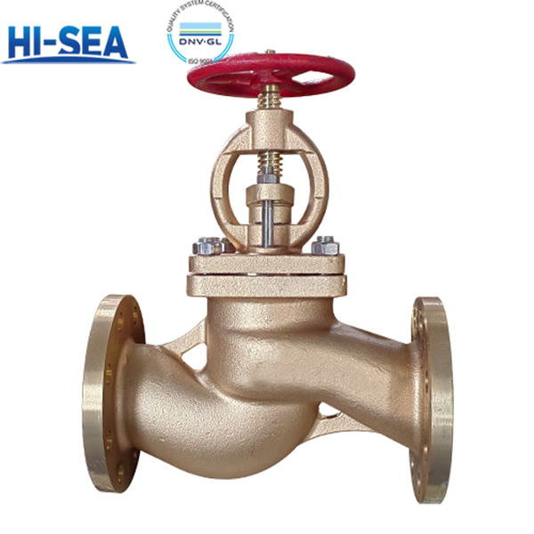
This is a flanged bronze stop check valve: the handwheel gives positive isolation, while the disc closes automatically against reverse flow the moment the handwheel is opened. It is specified for fresh water, seawater, lube oil, fuel oil, air, and steam up to 250 °C in ship piping systems. One body replaces a globe valve plus a separate check valve, so you cut one flanged joint, one spool piece and the leak path between them — weight and space that matter on a pump discharge header or a bilge line.
Body, bonnet and disc are cast bronze, supplied either as cast tin bronze ZCuSn5Pb5Zn5 for fresh water, lube oil, air and general utility lines, or as nickel-aluminium bronze ZCuAl9Fe4Ni4Mn2 where seawater and erosion-corrosion demand higher strength and better resistance to impingement. The stem is wrought aluminium bronze QAl9-2, chosen for torque capacity at the handwheel; because aluminium bronze carries a selective-phase (de-alloying) corrosion risk in seawater, an optional anti-de-alloying treatment can be applied on request. Soft goods follow the medium: PTFE for water, oil and air, flexible graphite for fuel oil and steam.
Design, materials, testing and marking follow GB/T 588-2026, with strength, tightness, wall thickness, dimensional and geometric tolerances referenced to GB/T 600-2023; AS/BS face-to-face dimensions follow GB/T 11698-2026. Every casting heat keeps at least three test bars stamped with the heat number and retained for not less than three years, so any valve can be traced back to its melt. Type testing runs on three samples, and every single valve is pressure-tested and inspected before shipment. Full test clauses, tolerances and weights are listed in the tables below.
Quick Selection Guide
Type A — CB/T 4196—2011 flange. Legacy Chinese marine flange drilling. Covers DN20–DN125 at PN25, DN125–DN150 at PN16, and runs right up to DN250 at PN10 — the only option forDN200/DN250.
Type AS — GB/T 9124.1—2019 flange, PN series. Dimensionally aligned with EN 1092-1, so it mates with European-style pipe flanges. The only option below DN20: DN15 starts here.
P vs S — soft goods. P (PTFE packing and gasket) for water, oil and air. S (flexible graphite) for fuel oil and steam — the standard specifies graphite for these media.
R vs F — sealing face. R (raised face) for standard spiral-wound or sheet gaskets; F (full flat face) where the mating flange is flat faced.
PN selection. PN10 = 1.0 MPa, PN16 = 1.6 MPa, PN25 = 2.5 MPa maximum working pressure — pick by line design pressure, not by pipe size.
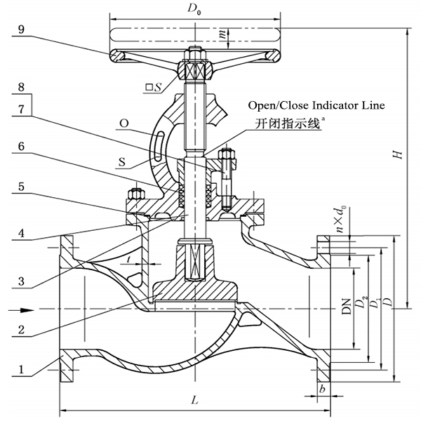
Basic Sructure of Marine Bronze Flanged Stop Check Valve Type A/AS
| Type | PN | Max. Working Pressure (MPa) | DN Range |
|---|---|---|---|
| A | 10 | 1.0 | 65 – 250 |
| A | 16 | 1.6 | 125, 150 |
| A | 25 | 2.5 | 20 – 125 |
| AS | 6 | 0.6 | 15 – 150 |
| AS | 16 | 1.6 | 65 – 150 |
| AS | 25 | 2.5 | 15 – 125 |
Notes: A = straight-through, CB/T 4196—2011 flange. AS = straight-through, GB/T 9124.1—2019 flange. PN16 in Type A is available at DN125 and DN150 only.
| PN | DN | L | H ≈ | Wall t | Handwheel D0 | Sq. Drive S | Lift | Mass |
|---|---|---|---|---|---|---|---|---|
| 10 | 65 | 290 | 309 | 6 | 140 | 12 | 17 | 17.3 |
| 10 | 80 | 310 | 339 | 6 | 160 | 14 | 20 | 20.1 |
| 10 | 100 | 350 | 364 | 6 | 180 | 14 | 25 | 29.7 |
| 10 | 125 | 400 | 414 | 7 | 200 | 17 | 32 | 40.1 |
| 10 | 150 | 480 | 468 | 7 | 200 | 17 | 38 | 55.8 |
| 10 | 200 | 600 | 586 | 8 | 360 | 27 | 59 | 135.0 |
| 10 | 250 | 730 | 753 | 9 | 450 | 32 | 65 | 211.0 |
| 16 | 125 | 400 | 450 | 7 | 250 | 22 | 32 | 53.3 |
| 16 | 150 | 480 | 505 | 8 | 280 | 24 | 38 | 62.6 |
| 25 | 20 | 150 | 217 | 5 | 80 | 8 | 7 | 5.4 |
| 25 | 25 | 160 | 217 | 5 | 80 | 8 | 7 | 6.0 |
| 25 | 32 | 180 | 236 | 5 | 100 | 9 | 9 | 7.0 |
| 25 | 40 | 200 | 260 | 5 | 120 | 11 | 11 | 9.5 |
| 25 | 50 | 230 | 288 | 6 | 140 | 12 | 14 | 12.3 |
| 25 | 65 | 290 | 334 | 7 | 160 | 14 | 17 | 20.8 |
| 25 | 80 | 310 | 362 | 7 | 200 | 17 | 20 | 28.0 |
| 25 | 100 | 350 | 417 | 8 | 250 | 22 | 25 | 41.4 |
| 25 | 125 | 400 | 481 | 9 | 280 | 24 | 32 | 68.7 |
Notes: Mass is theoretical, for cast tin bronze; deduct 8 % when nickel-aluminium bronze is specified. L = face-to-face length. H ≈ = centreline to handwheel, open. S = handwheel square-hole across flats.
| PN | DN | D | D1 | D2 | d0 | b | n | Bolt |
|---|---|---|---|---|---|---|---|---|
| 10 | 65 | 155 | 123 | 104 | 15 | 14 | 6 | M14 |
| 10 | 80 | 170 | 138 | 118 | 15 | 14 | 8 | M14 |
| 10 | 100 | 190 | 158 | 138 | 15 | 14 | 8 | M14 |
| 10 | 125 | 215 | 183 | 164 | 15 | 14 | 10 | M14 |
| 10 | 150 | 240 | 208 | 190 | 15 | 14 | 12 | M14 |
| 10 | 200 | 310 | 273 | 250 | 17 | 17 | 12 | M16 |
| 10 | 250 | 380 | 336 | 310 | 21 | 21 | 14 | M20 |
| 16 | 125 | 225 | 187 | 168 | 17 | 19 | 10 | M16 |
| 16 | 150 | 255 | 217 | 196 | 17 | 19 | 12 | M16 |
| 25 | 20 | 95 | 68 | 48 | 13 | 11 | 4 | M12 |
| 25 | 25 | 105 | 73 | 56 | 13 | 12 | 4 | M12 |
| 25 | 32 | 115 | 83 | 64 | 15 | 13 | 6 | M14 |
| 25 | 40 | 125 | 93 | 74 | 15 | 13 | 6 | M14 |
| 25 | 50 | 135 | 103 | 84 | 15 | 13 | 6 | M14 |
| 25 | 65 | 170 | 132 | 110 | 17 | 15 | 8 | M16 |
| 25 | 80 | 185 | 147 | 126 | 17 | 16 | 8 | M16 |
| 25 | 100 | 205 | 167 | 146 | 17 | 16 | 10 | M16 |
| 25 | 125 | 240 | 196 | 172 | 21 | 19 | 10 | M20 |
Notes: D = flange OD. D1 = bolt circle. D2 = sealing face diameter. d0 = bolt hole. b = flange thickness. n = number of bolt holes. Th. = bolt thread.
| PN | DN | L | H ≈ | Wall t | Handwheel D0 | Sq. Drive S | Lift | Mass |
|---|---|---|---|---|---|---|---|---|
| 6 | 15 | 130 | 217 | 4 | 80 | 8 | 7 | 4.8 |
| 6 | 20 | 150 | 217 | 4 | 80 | 8 | 7 | 5.3 |
| 6 | 25 | 160 | 217 | 4 | 80 | 8 | 7 | 5.9 |
| 6 | 32 | 180 | 236 | 5 | 100 | 9 | 9 | 7.4 |
| 6 | 40 | 200 | 260 | 5 | 120 | 11 | 11 | 8.8 |
| 6 | 50 | 230 | 288 | 5 | 140 | 12 | 14 | 12.7 |
| 6 | 65 | 290 | 308 | 6 | 140 | 12 | 17 | 16.7 |
| 6 | 80 | 310 | 339 | 6 | 160 | 14 | 20 | 24.2 |
| 6 | 100 | 350 | 364 | 6 | 180 | 14 | 25 | 35.3 |
| 6 | 125 | 400 | 414 | 7 | 200 | 17 | 32 | 47.5 |
| 6 | 150 | 480 | 468 | 7 | 200 | 17 | 38 | 69.4 |
| 16 | 65 | 290 | 334 | 6 | 160 | 14 | 19 | 22.6 |
| 16 | 80 | 310 | 362 | 6 | 200 | 17 | 20 | 31.2 |
| 16 | 100 | 350 | 417 | 6 | 250 | 20 | 25 | 47.6 |
| 16 | 125 | 400 | 450 | 7 | 250 | 22 | 32 | 57.0 |
| 16 | 150 | 480 | 505 | 8 | 280 | 24 | 38 | 69.0 |
| 25 | 15 | 130 | 217 | 5 | 80 | 8 | 7 | 5.6 |
| 25 | 20 | 150 | 217 | 5 | 80 | 8 | 7 | 6.1 |
| 25 | 25 | 160 | 217 | 5 | 80 | 8 | 7 | 6.4 |
| 25 | 32 | 180 | 236 | 5 | 100 | 9 | 9 | 9.0 |
| 25 | 40 | 200 | 260 | 5 | 120 | 11 | 11 | 11.2 |
| 25 | 50 | 230 | 288 | 6 | 140 | 12 | 14 | 15.6 |
| 25 | 65 | 290 | 334 | 7 | 160 | 14 | 19 | 22.8 |
| 25 | 80 | 310 | 362 | 7 | 200 | 17 | 20 | 31.4 |
| 25 | 100 | 350 | 417 | 8 | 250 | 20 | 25 | 50.4 |
| 25 | 125 | 400 | 481 | 9 | 280 | 24 | 32 | 79.3 |
| PN | DN | D | D1 | D2 | d0 | b | n | Bolt |
|---|---|---|---|---|---|---|---|---|
| 6 | 15 | 80 | 55 | 40 | 11 | 12 | 4 | M10 |
| 6 | 20 | 90 | 65 | 50 | 11 | 12 | 4 | M10 |
| 6 | 25 | 100 | 75 | 60 | 11 | 14 | 4 | M10 |
| 6 | 32 | 120 | 90 | 70 | 14 | 15 | 4 | M12 |
| 6 | 40 | 130 | 100 | 80 | 14 | 16 | 4 | M12 |
| 6 | 50 | 140 | 110 | 90 | 14 | 17 | 4 | M12 |
| 6 | 65 | 160 | 130 | 110 | 14 | 17 | 4 | M12 |
| 6 | 80 | 190 | 150 | 128 | 18 | 19 | 4 | M16 |
| 6 | 100 | 210 | 170 | 148 | 18 | 20 | 4 | M16 |
| 6 | 125 | 240 | 200 | 178 | 18 | 20 | 8 | M16 |
| 6 | 150 | 265 | 225 | 202 | 18 | 20 | 8 | M16 |
| 16 | 65 | 185 | 145 | 122 | 18 | 17 | 4 * | M16 |
| 16 | 80 | 200 | 160 | 138 | 18 | 19 | 8 | M16 |
| 16 | 100 | 220 | 180 | 158 | 18 | 20 | 8 | M16 |
| 16 | 125 | 250 | 210 | 188 | 18 | 22 | 8 | M16 |
| 16 | 150 | 285 | 240 | 212 | 22 | 22 | 8 | M20 |
| 25 | 15 | 95 | 65 | 45 | 14 | 12 | 4 | M12 |
| 25 | 20 | 105 | 75 | 58 | 14 | 12 | 4 | M12 |
| 25 | 25 | 115 | 85 | 68 | 14 | 14 | 4 | M12 |
| 25 | 32 | 140 | 100 | 78 | 18 | 15 | 4 | M16 |
| 25 | 40 | 150 | 110 | 88 | 18 | 16 | 4 | M16 |
| 25 | 50 | 165 | 125 | 102 | 18 | 17 | 4 | M16 |
| 25 | 65 | 185 | 145 | 122 | 18 | 17 | 8 | M16 |
| 25 | 80 | 200 | 160 | 138 | 18 | 19 | 8 | M16 |
| 25 | 100 | 235 | 190 | 162 | 22 | 20 | 8 | M20 |
| 25 | 125 | 270 | 220 | 188 | 26 | 26 | 8 | M24 |
Notes: * PN16 DN65 — bolt-hole coordination to be confirmed against the mating flange when GB/T 9124.1—2019 flanges are used. D = flange OD. D1 = bolt circle. D2 = sealing face diameter. d0 = bolt hole. b = flange thickness. n = number of bolt holes.
| Component | Material | Grade | Standard | Code |
|---|---|---|---|---|
| Body, bonnet, disc | Cast tin bronze | ZCuSn5Pb5Zn5 | GB/T 1176—2013 | Q1 |
| Body, bonnet, disc | Nickel-aluminium bronze | ZCuAl9Fe4Ni4Mn2 | GB/T 1176—2013 | Q2 |
| Stem | Aluminium bronze bar | QAl9-2 | GB/T 4423—2020 | — |
| Packing | PTFE braided packing | F4SD | JB/T 6626—2011 | P |
| Packing | Flexible graphite | RSM | CB/T 3589—1994 | S |
| Gasket | PTFE | PTFE | QB/T 4041—2010 | P |
| Gasket | Flexible graphite | RSM | CB/T 3589—1994 | S |
| Stud | Stainless steel | A4-70 | GB/T 3098.6—2023 | — |
| Nut | Stainless steel | A4-50 | GB/T 3098.15—2023 | — |
| Handwheel | Stainless steel casting | CF8 | GB/T 12230—2023 | — |
Quality Assurance & Testing
Pressure Testing: 100% shell strength and tightness tests before shipment, per GB/T 600-2023.
Material Traceability: Each casting heat retains at least 3 test bars stamped with the heat number, stored for ≥ 3 years.
Dimensional Accuracy: AS/BS face-to-face dimensions strictly follow GB/T 11698-2026.
Weight Control: Theoretical weight based on cast tin bronze. Positive deviation ≤ 4%. (Deduct 8% for Q2).
FAQ
Is this one valve doing two jobs — stop valve and check valve?
Yes. Closed, it isolates. Open, the disc seats against reverse flow on its own. It is not a substitute where the check function must remain independent of the isolating function — if your classification society requires two separate isolation boundaries, keep them separate. For normal machinery-space piping it replaces both and removes a flanged joint.
Tin bronze or nickel-aluminium bronze? Which one should I choose?
Cast Tin Bronze (ZCuSn5Pb5Zn5): The cost-effective standard for low-pressure, ambient-temperature, and low-velocity seawater systems (e.g., ballast water, bilge lines, fire mains). It offers reliable performance and is highly economical for general shipboard piping.
Nickel-Aluminium Bronze (ZCuAl9Fe4Ni4Mn2): The recommended upgrade for high-pressure, high-velocity, or sand-laden seawater systems (e.g., main seawater cooling lines, pump discharges). It provides significantly higher mechanical strength and superior erosion-corrosion resistance. The standard (GB/T 588-2026) recommends Q2 for critical seawater duty. It is also approximately 8% lighter than Q1
What is the real difference between A type and AS type?
Only the flange. A type uses CB/T 4196-2011 flange dimensions and sealing face; AS type uses GB/T 9124.1-2019. The valve internals, materials and pressure classes are identical. Match the code to the flange on your pipe, not to the valve. If your line was built to CB/T 4196, an AS valve will not bolt up, and the reverse is also true.