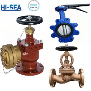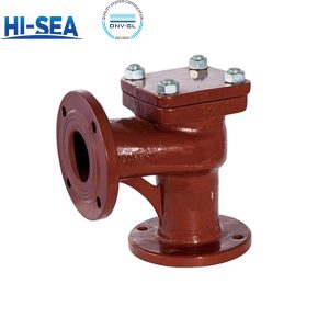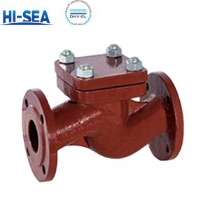
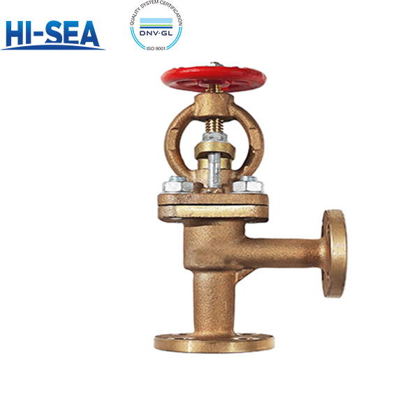
overview
Positioning and duty. The B/BS valve is an angle-pattern stop check valve: the disc is guided by the stem for manual shut-off, and closes against reverse flow without any external signal. It is specified for fresh water, seawater, lube oil, fuel oil, air and steam up to 250 °C in ship piping systems, in pressure classes from PN6 to PN25 and sizes from DN15 to DN250. The engineering case for the angle body is layout, not performance — it absorbs the 90° turn that already exists at a bulkhead penetration or a pump discharge, so one valve replaces a bend plus a straight-pattern valve and two flange pairs.
Why the material split matters. The body, bonnet and disc are cast in either tin bronze (ZCuSn5Pb5Zn5) or nickel-aluminium bronze (ZCuAl9Fe4Ni4Mn2). Tin bronze is the cost-effective answer for fresh water, lube oil, air and low-pressure seawater; nickel-aluminium bronze carries higher initial material cost but is the grade the standard points to for seawater service, and it delivers a lower finished weight. The stem is aluminium bronze QAl9-2 for strength; bolting is A4-70 studs with A4-50 nuts and a CF8 stainless handwheel, so the fasteners do not become the corrosion limit on a bronze body.
Standards behind it. Design, marking, testing and acceptance follow GB/T 588—2026, with strength, tightness, wall thickness, tolerances, assembly and appearance referenced to GB/T 600—2023. Face-to-face length of the BS type is controlled to GB/T 11698—2026, and every casting heat is backed by three furnace-numbered test bars retained for at least three years. Full dimensional and materials data are in the tables below.
Quick Selection Guide
B or BS (flange standard):
B type: flange dimensions and sealing face to CB/T 4196—2011. Best suited for replacement and repair on vessels built to Chinese ship piping practice, and for yards already running CB flanges.
BS type: flange dimensions and sealing face to GB/T 9124.1—2019 (PN series). Recommended when the mating pipe flanges are ordered to the GB PN system.
These two are not interchangeable. Confirm the mating flange standard before ordering — this is the single most common ordering error on this product.
Angle (B/BS) or straight (A/AS):
Angle pattern: for corners, bulkhead penetrations and pump discharges where the line turns anyway. Saves space and one fitting.
Straight pattern: for long straight runs and anywhere line pressure margin is tight. The 90° body adds one flow turn, so pressure drop is higher than the straight pattern at the same DN. Where a pressure budget is already tight, take the straight type.
Body material Q1 or Q2:
Q1 tin bronze (ZCuSn5Pb5Zn5): for fresh water, lube oil, air low-pressure/ambient-temperature seawater.It offers reliable, proven performance for general shipboard utility lines, Lower first cost.
Q2 nickel-aluminium bronze (ZCuAl9Fe4Ni4Mn2): for seawater and for critical systems where a shutdown is expensive. Higher initial material cost, offset by longer service life in aggressive media. Note that Q2 parts are about 8% lighter, so the two are not directly comparable on a pure cost-per-kilo basis.
Packing and gasket P or S:
P (PTFE): fresh water, seawater, lube oil, air.
S (flexible graphite): mandatory for fuel oil and steam per the standard. Do not substitute PTFE on these media.
Sealing face R or F: match the mating flange — R (raised face) or F (full flat). Mismatched faces leak; they are not a commercial choice.
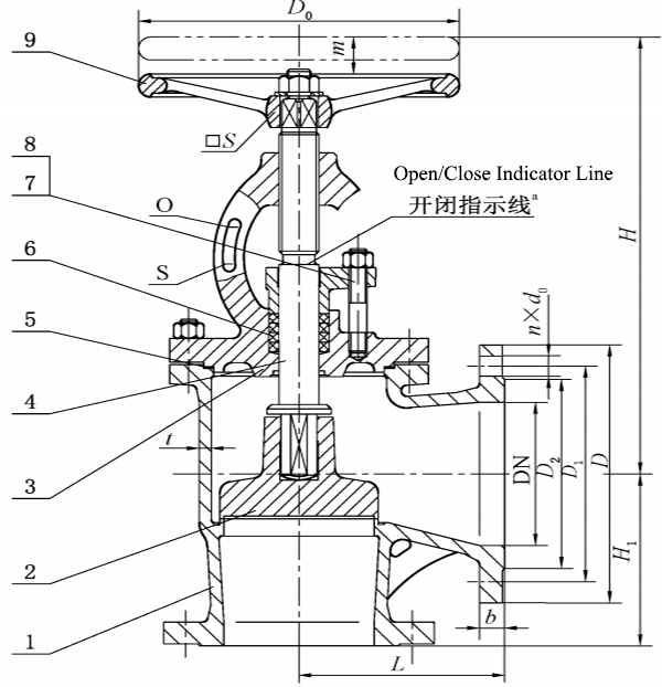
Basic Sructure Of Marine Bronze Flanged Stop Check Valve Type B/BS
| Type | Flange Standard | PN | Max Working Pressure (MPa) | DN Range |
|---|---|---|---|---|
| B | CB/T 4196-2011 | 10 | 1.0 | 65 – 250 |
| B | CB/T 4196-2011 | 16 | 1.6 | 125, 150 |
| B | CB/T 4196-2011 | 25 | 2.5 | 20 – 125 |
| BS | GB/T 9124.1-2019 | 6 | 0.6 | 15 – 150 |
| BS | GB/T 9124.1-2019 | 16 | 1.6 | 65 – 150 |
| BS | GB/T 9124.1-2019 | 25 | 2.5 | 15 – 125 |
| PN | DN | L | H ≈ | H1 | Wall Thickness t | Handwheel D0 | Handwheel S | Lift | Weight |
|---|---|---|---|---|---|---|---|---|---|
| 10 | 65 | 115 | 275 | 115 | 6 | 140 | 12 | 17 | 14.9 |
| 10 | 80 | 125 | 298 | 125 | 6 | 160 | 14 | 20 | 17.9 |
| 10 | 100 | 150 | 315 | 135 | 6 | 180 | 14 | 25 | 24.2 |
| 10 | 125 | 175 | 354 | 155 | 7 | 200 | 17 | 32 | 35.2 |
| 10 | 150 | 180 | 395 | 160 | 7 | 200 | 17 | 38 | 47.9 |
| 10 | 200 | 275 | 460 | 275 | 8 | 360 | 27 | 59 | 99.5 |
| 10 | 250 | 325 | 547 | 325 | 9 | 450 | 32 | 65 | 185.0 |
| 16 | 125 | 175 | 393 | 155 | 7 | 250 | 22 | 32 | 45.1 |
| 16 | 150 | 180 | 433 | 160 | 8 | 280 | 24 | 38 | 58.3 |
| 25 | 20 | 75 | 203 | 75 | 5 | 80 | 8 | 7 | 5.2 |
| 25 | 25 | 80 | 203 | 80 | 5 | 80 | 8 | 7 | 5.8 |
| 25 | 32 | 85 | 216 | 85 | 5 | 100 | 9 | 9 | 6.7 |
| 25 | 40 | 90 | 236 | 90 | 5 | 120 | 11 | 11 | 8.5 |
| 25 | 50 | 95 | 258 | 95 | 6 | 140 | 12 | 14 | 11.0 |
| 25 | 65 | 115 | 301 | 115 | 7 | 160 | 14 | 17 | 18.5 |
| 25 | 80 | 125 | 321 | 125 | 7 | 200 | 17 | 20 | 25.9 |
| 25 | 100 | 135 | 368 | 135 | 8 | 250 | 22 | 25 | 36.1 |
| 25 | 125 | 155 | 421 | 155 | 9 | 280 | 24 | 32 | 55.3 |
L = face-to-face (structural length); H ≈ = centre to handwheel top, open; H1 = centre to end face; m = lift; S = handwheel square hole across flats. Weights are for cast tin bronze; reduce by 8 % for nickel-aluminium bronze. Structural length tolerance for B type is per the construction drawing.
| PN | DN | D | D1 | D2 | d0 | b | n | Th. |
|---|---|---|---|---|---|---|---|---|
| 10 | 65 | 155 | 123 | 104 | 15 | 14 | 6 | M14 |
| 10 | 80 | 170 | 138 | 118 | 15 | 14 | 8 | M14 |
| 10 | 100 | 190 | 158 | 138 | 15 | 14 | 8 | M14 |
| 10 | 125 | 215 | 183 | 164 | 15 | 14 | 10 | M14 |
| 10 | 150 | 240 | 208 | 190 | 15 | 14 | 12 | M14 |
| 10 | 200 | 310 | 273 | 250 | 17 | 17 | 12 | M16 |
| 10 | 250 | 380 | 336 | 310 | 21 | 21 | 14 | M20 |
| 16 | 125 | 225 | 187 | 168 | 17 | 19 | 10 | M16 |
| 16 | 150 | 255 | 217 | 196 | 17 | 19 | 12 | M16 |
| 25 | 20 | 95 | 68 | 48 | 13 | 11 | 4 | M12 |
| 25 | 25 | 105 | 73 | 56 | 13 | 12 | 4 | M12 |
| 25 | 32 | 115 | 83 | 64 | 15 | 13 | 6 | M14 |
| 25 | 40 | 125 | 93 | 74 | 15 | 13 | 6 | M14 |
| 25 | 50 | 135 | 103 | 84 | 15 | 13 | 6 | M14 |
| 25 | 65 | 170 | 132 | 110 | 17 | 15 | 8 | M16 |
| 25 | 80 | 185 | 147 | 126 | 17 | 16 | 8 | M16 |
| 25 | 100 | 205 | 167 | 146 | 17 | 16 | 10 | M16 |
| 25 | 125 | 240 | 196 | 172 | 21 | 19 | 10 | M20 |
| PN | DN | L | H1 | H ≈ | Wall Thickness t | Handwheel D0 | Handwheel S | Lift | Weight |
|---|---|---|---|---|---|---|---|---|---|
| 6 | 15 | 90 | 90 | 203 | 4 | 80 | 8 | 7 | 4.7 |
| 6 | 20 | 95 | 95 | 203 | 4 | 80 | 8 | 7 | 5.2 |
| 6 | 25 | 100 | 100 | 203 | 4 | 80 | 8 | 7 | 5.8 |
| 6 | 32 | 105 | 105 | 216 | 5 | 100 | 9 | 9 | 7.2 |
| 6 | 40 | 115 | 115 | 236 | 5 | 120 | 11 | 11 | 9.0 |
| 6 | 50 | 125 | 125 | 258 | 5 | 140 | 12 | 14 | 13.8 |
| 6 | 65 | 145 | 145 | 275 | 6 | 140 | 12 | 17 | 15.2 |
| 6 | 80 | 155 | 155 | 298 | 6 | 160 | 14 | 20 | 23.3 |
| 6 | 100 | 175 | 175 | 315 | 6 | 180 | 14 | 25 | 30.6 |
| 6 | 125 | 200 | 200 | 354 | 7 | 200 | 17 | 32 | 45.7 |
| 6 | 150 | 225 | 225 | 376 | 7 | 200 | 17 | 38 | 63.6 |
| 16 | 65 | 145 | 145 | 301 | 6 | 160 | 14 | 19 | 21.2 |
| 16 | 80 | 155 | 155 | 321 | 6 | 200 | 17 | 20 | 29.9 |
| 16 | 100 | 175 | 175 | 368 | 6 | 250 | 20 | 25 | 41.5 |
| 16 | 125 | 200 | 200 | 393 | 7 | 250 | 22 | 32 | 51.3 |
| 16 | 150 | 225 | 225 | 433 | 8 | 280 | 24 | 38 | 68.9 |
| 25 | 15 | 90 | 90 | 203 | 5 | 80 | 8 | 7 | 5.3 |
| 25 | 20 | 95 | 95 | 203 | 5 | 80 | 8 | 7 | 5.8 |
| 25 | 25 | 100 | 100 | 203 | 5 | 80 | 8 | 7 | 6.7 |
| 25 | 32 | 105 | 105 | 216 | 5 | 100 | 9 | 9 | 8.6 |
| 25 | 40 | 115 | 115 | 236 | 5 | 120 | 11 | 11 | 11.8 |
| 25 | 50 | 125 | 125 | 258 | 6 | 140 | 12 | 14 | 15.4 |
| 25 | 65 | 145 | 145 | 301 | 7 | 160 | 14 | 19 | 21.4 |
| 25 | 80 | 155 | 155 | 321 | 7 | 200 | 17 | 20 | 30.2 |
| 25 | 100 | 175 | 175 | 368 | 8 | 250 | 20 | 25 | 44.0 |
| 25 | 125 | 200 | 200 | 421 | 9 | 280 | 24 | 32 | 64.7 |
BS Type — Flange Connection Dimensions, GB/T 9124.1-2019 (Unit: mm)
| PN | DN | D | D1 | D2 | d0 | b | n | Th. |
|---|---|---|---|---|---|---|---|---|
| 6 | 15 | 80 | 55 | 40 | 11 | 12 | 4 | M10 |
| 6 | 20 | 90 | 65 | 50 | 11 | 12 | 4 | M10 |
| 6 | 25 | 100 | 75 | 60 | 11 | 14 | 4 | M10 |
| 6 | 32 | 120 | 90 | 70 | 14 | 15 | 4 | M12 |
| 6 | 40 | 130 | 100 | 80 | 14 | 16 | 4 | M12 |
| 6 | 50 | 140 | 110 | 90 | 14 | 17 | 4 | M12 |
| 6 | 65 | 160 | 130 | 110 | 14 | 17 | 4 | M12 |
| 6 | 80 | 190 | 150 | 128 | 18 | 19 | 4 | M16 |
| 6 | 100 | 210 | 170 | 148 | 18 | 20 | 4 | M16 |
| 6 | 125 | 240 | 200 | 178 | 18 | 20 | 8 | M16 |
| 6 | 150 | 265 | 225 | 202 | 18 | 20 | 8 | M16 |
| 16 | 65 | 185 | 145 | 122 | 18 | 17 | 4 a | M16 |
| 16 | 80 | 200 | 160 | 138 | 18 | 19 | 8 | M16 |
| 16 | 100 | 220 | 180 | 158 | 18 | 20 | 8 | M16 |
| 16 | 125 | 250 | 210 | 188 | 18 | 22 | 8 | M16 |
| 16 | 150 | 285 | 240 | 212 | 22 | 22 | 8 | M20 |
| 25 | 15 | 95 | 65 | 45 | 14 | 12 | 4 | M12 |
| 25 | 20 | 105 | 75 | 58 | 14 | 12 | 4 | M12 |
| 25 | 25 | 115 | 85 | 68 | 14 | 14 | 4 | M12 |
| 25 | 32 | 140 | 100 | 78 | 18 | 15 | 4 | M16 |
| 25 | 40 | 150 | 110 | 88 | 18 | 16 | 4 | M16 |
| 25 | 50 | 165 | 125 | 102 | 18 | 17 | 4 | M16 |
| 25 | 65 | 185 | 145 | 122 | 18 | 17 | 8 | M16 |
| 25 | 80 | 200 | 160 | 138 | 18 | 19 | 8 | M16 |
| 25 | 100 | 235 | 190 | 162 | 22 | 20 | 8 | M20 |
| 25 | 125 | 270 | 220 | 188 | 26 | 26 | 8 | M24 |
Materials of Construction
| Part | Material | Grade | Standard |
|---|---|---|---|
| Body, bonnet, disc | Cast tin bronze | ZCuSn5Pb5Zn5 | GB/T 1176-2013 |
| Body, bonnet, disc | Nickel-aluminium bronze | ZCuAl9Fe4Ni4Mn2 | GB/T 1176-2013 |
| Stem | Aluminium bronze (wrought) | QAl9-2 | GB/T 4423-2020 |
| Packing | PTFE braided packing | F4SD | JB/T 6626-2011 |
| Packing | Flexible graphite | RSM | CB/T 3589-1994 |
| Gasket | PTFE | PTFE | QB/T 4041-2010 |
| Gasket | Flexible graphite | RSM | CB/T 3589-1994 |
| Stud | Stainless steel | A4-70 | GB/T 3098.6-2023 |
| Nut | Stainless steel | A4-50 | GB/T 3098.15-2023 |
| Handwheel | Stainless steel casting | CF8 | GB/T 12230-2023 |
trength and tightness:verified per GB/T 588-2026 5.2 / 5.3, which reference GB/T 600-2023 clauses 4.14 and 4.15. Test procedures are 6.1 and 6.2 (GB/T 600-2023 5.1.1.2 and 5.1.2.2). Test pressures follow GB/T 600-2023 — specify them on the datasheet at enquiry rather than assuming a multiplier.
Wall thickness and tolerances:wall thickness to GB/T 600-2023 4.2, thickness tolerance to 4.5.1, linear dimensional tolerance to 4.5, geometric tolerance to 4.7 checked to GB/T 1958.
Face-to-face:B pattern per the construction drawing; BS pattern per GB/T 11698-2026. This is the clause that governs whether a replacement valve drops into an existing spool.
Assembly:per GB/T 600-2023 4.10 (5.6), verified visually and by caliper (6.5). Appearance per 4.11 (5.7).
Weight:theoretical weight as tabulated; positive deviation must not exceed 4 % of theoretical (5.8). Weighing on a scale with 0.01 kg resolution (6.7). This matters for lifting plans and freight — and it is why we quote per piece, not per kilo.
Material traceability:each casting heat retains at least 3 numbered test bars with the heat number, kept not less than 3 years (5.1.2). Castings are released by heat; every finished valve is factory-tested individually (7.3.2).
FAQ
B or BS — how do I tell which one my line needs?
Look at the counter-flange, not at the valve. B uses CB/T 4196-2011 connecting dimensions and sealing face — the marine shipyard pattern. BS uses GB/T 9124.1-2019 — the PN-series steel pipe flange pattern. Same DN and PN does not mean the same drilling; the bolt circle, hole count and thread can all differ. Send us the mating flange drawing (D, D1, hole count, thread, raised or full flat face) and we will confirm the pattern before production. The standard itself flags bolt-hole coordination as a check point for GB/T 9124.1 flanges.
My space is tight — should I take the angle pattern or the straight one?
The angle body turns the flow 90° inside the casting, so it replaces one elbow and the valve: shorter installed envelope, one less flanged joint, one less leak path at bulkheads and corners. The trade-off is real — turning loss plus disc resistance gives a higher pressure drop than a straight-pattern valve of the same DN. On pump discharges with adequate head margin this is normally absorbed; on gravity or low-head lines, run the numbers before you swap a straight valve for an angle one.
Is this a check valve, or a stop valve?
Neither, on its own — this is the combined type, also ordered as an SDNR (screw-down non-return) valve. Closing the handwheel isolates the line; with the handwheel open the disc blocks reverse flow automatically. If you only need manual isolation, specify the GB/T 587 stop valve series; if you only need non-return, specify the GB/T 589 check valve series.