Overview
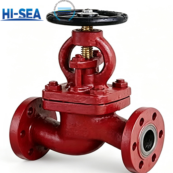
The A and AS types are straight-pattern flanged stop valves built for isolation duty in shipboard piping systems handling seawater, fresh water, lubricating oil and fuel oil. Both share one valve body design; the difference is the flange interface — the A type is drilled to CB/T 4196, the AS type to the GB/T 9124.1 PN series, which extends coverage up to DN300 at PN6. Manual handwheel operation, bolted bonnet, and a metal-seated disc give predictable isolation where elastomer-seated valves would age.
Material selection follows the medium, not the price list. Body and bonnet are cast in HT200 grey iron for general sea water and fresh water service, or QT400-18 ductile iron where vibration, water hammer or heavier piping loads are expected; both options share the same face-to-face and flange dimensions, so a late material upgrade does not force a piping change. The trim is all bronze — tin-bronze disc, aluminium-bronze seat, aluminium-bronze stem — which resists galling and marine corrosion without a soft seat insert. Packing and gasket are PTFE for water and lube oil service, and flexible graphite where the medium is fuel oil. Note that aluminium bronze carries a dealuminisation risk in sea water; an anti-dealuminisation treatment can be specified for long-immersion seawater lines.
Every valve is designed, manufactured and accepted against GB/T 590—2026, with strength, tightness, wall thickness, dimensional and geometric tolerances referenced to GB/T 600—2023. Mass is controlled to within +4 % of theoretical, castings are traceable by heat number for a minimum of three years, and marking follows GB/T 3032. Clause-by-clause verification data is listed in the compliance section below.
Quick Selection Guide
Flange standard — the primary decision
Type A : flanges to CB/T 4196—2011, the ship-service flange series. Best suited for conventional ship piping built around CB/T 4196 flanges. Range: PN10 DN65–150, PN16 DN20–50.
Type AS : flanges to GB/T 9124.1—2019, the PN-series flanges. Recommended when the mating flange follows GB/T 9124.1, or when PN6 duty or sizes up to DN300 are required. Range: PN6 DN50–300, PN10 DN65–250, PN16 DN20–50.
Body material
HT200 gray iron: cost-effective default for low-pressure seawater, fresh water and lube oil.
QT400-18 ductile iron: higher initial material cost; recommended where higher strength or impact resistance is required in critical systems. Weight differs by body material — the two are not directly comparable on a pure cost-per-kilo basis.
Packing / gasket
PTFE (code P): general service.
Flexible graphite (code S): required for fuel oil per the standard.
Handwheel material
Ductile iron QT400-15 — cost-effective default. Best suited for general shipboard piping in seawater, fresh water or lube oil service with normal handwheel operation. Handwheel OD stays at 200 mm or below up to DN150, so torque demand remains moderate.
Cast steel ZG230-450 — upgrade for higher load. Higher initial material cost. Recommended when sizing up — handwheel OD reaches 450 mm at DN300 — or when the handwheel is likely to take knocks during handling. Delivers longer service life in heavy-duty service without changing the valve’s pressure rating.
Basic Sructure Of Marine Cast Iron Flanged Stop Valve — A / AS Type
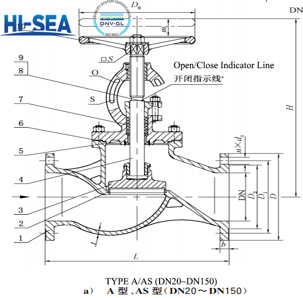
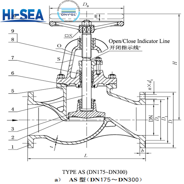
Basic Parameters (Table 1) — Types A / AS (PN, MPa, DN)
| VALVE TYPE |
PN |
MAX WORKING PRESSURE (MPa) |
NOMINAL SIZE (DN) |
| Type A |
10 |
1.0 |
65–150 |
| Type A |
16 |
1.6 |
20–50 |
| Type AS |
6 |
0.6 |
50–300 |
| Type AS |
10 |
1.0 |
65–250 |
| Type AS |
16 |
1.6 |
20–50 |
Type A flanges to CB/T 4196-2011; Type AS flanges to GB/T 9124.1-2019.
Dimensions & Weight (Table 2) — Type A, PN10 (mm, kg)
| DN |
L |
H≈ |
t |
D |
D1 |
D2 |
d0 |
b |
n |
Th |
m |
MASS |
| 65 |
290 |
310 |
9 |
155 |
123 |
104 |
15 |
15 |
6 |
M14 |
18 |
18.9 |
| 80 |
310 |
345 |
9 |
170 |
138 |
118 |
15 |
15 |
8 |
M14 |
24 |
23.0 |
| 100 |
350 |
374 |
10 |
190 |
158 |
138 |
15 |
15 |
8 |
M14 |
35 |
31.0 |
| 125 |
400 |
426 |
10 |
215 |
183 |
164 |
15 |
15 |
10 |
M14 |
44 |
39.3 |
| 150 |
480 |
487 |
11 |
240 |
208 |
190 |
15 |
16 |
12 |
M14 |
57 |
55.5 |
L = face-to-face; H≈ = centre to handwheel, open; t = wall thickness; m = travel. Mass is theoretical; positive tolerance +4%.
Dimensions & Weight (Table 2) — Type A, PN16 (mm, kg)
| DN |
L |
H≈ |
t |
D |
D1 |
D2 |
d0 |
b |
n |
Th |
m |
MASS |
| 20 |
150 |
217 |
7 |
95 |
68 |
48 |
13 |
14 |
4 |
M12 |
7 |
5.7 |
| 25 |
160 |
217 |
7 |
105 |
73 |
56 |
13 |
14 |
4 |
M12 |
7 |
6.0 |
| 32 |
180 |
236 |
7 |
115 |
83 |
64 |
15 |
15 |
6 |
M14 |
9 |
7.0 |
| 40 |
200 |
260 |
8 |
125 |
93 |
74 |
15 |
15 |
6 |
M14 |
11 |
9.2 |
| 50 |
230 |
288 |
8 |
135 |
103 |
84 |
15 |
16 |
6 |
M14 |
14 |
11.9 |
Dimensions & Weight (Table 3) — Type AS, PN6 (mm, kg)
| DN |
L |
H≈ |
t |
D |
D1 |
D2 |
d0 |
b |
n |
Th |
m |
MASS |
| 50 |
230 |
288 |
8 |
140 |
110 |
90 |
14 |
16 |
4 |
M12 |
14 |
12.2 |
| 65 |
290 |
310 |
9 |
160 |
130 |
110 |
14 |
18 |
4 |
M12 |
18 |
19.2 |
| 80 |
310 |
345 |
9 |
190 |
150 |
128 |
18 |
18 |
4 |
M16 |
24 |
23.8 |
| 100 |
350 |
374 |
10 |
210 |
170 |
148 |
18 |
18 |
4 |
M16 |
35 |
34.5 |
| 125 |
400 |
426 |
10 |
240 |
200 |
178 |
18 |
20 |
8 |
M16 |
44 |
42.5 |
| 150 |
480 |
487 |
11 |
265 |
225 |
202 |
18 |
20 |
8 |
M16 |
57 |
58.7 |
| 175 |
540 |
557 |
11 |
295 |
255 |
232 |
18 |
22 |
8 |
M16 |
60 |
76.8 |
| 200 |
600 |
614 |
11 |
320 |
280 |
258 |
18 |
22 |
8 |
M16 |
68 |
102.0 |
| 250 |
730 |
703 |
13 |
375 |
335 |
312 |
22 |
24 |
12 |
M20 |
80 |
158.0 |
| 300 |
850 |
799 |
13 |
440 |
395 |
365 |
22 |
24 |
12 |
M20 |
100 |
218.0 |
Dimensions & Weight (Table 3) — Type AS, PN10 (mm, kg)
| DN |
L |
H≈ |
t |
D |
D1 |
D2 |
d0 |
b |
n |
Th |
m |
MASS |
| 65 |
290 |
310 |
9 |
185 |
145 |
122 |
18 |
20 |
4 |
M16 |
18 |
21.6 |
| 80 |
310 |
345 |
9 |
200 |
160 |
138 |
18 |
22 |
4 |
M16 |
24 |
26.0 |
| 100 |
350 |
374 |
10 |
220 |
180 |
158 |
18 |
24 |
4 |
M16 |
35 |
35.0 |
| 125 |
400 |
426 |
10 |
250 |
210 |
188 |
18 |
24 |
8 |
M16 |
44 |
44.3 |
| 150 |
480 |
487 |
11 |
285 |
240 |
212 |
22 |
26 |
8 |
M20 |
57 |
62.7 |
| 175 |
540 |
557 |
11 |
315 |
270 |
242 |
22 |
26 |
8 |
M20 |
60 |
80.3 |
| 200 |
600 |
621 |
11 |
340 |
295 |
268 |
22 |
28 |
8 |
M20 |
68 |
106.0 |
| 250 |
730 |
721 |
13 |
395 |
350 |
320 |
22 |
28 |
12 |
M20 |
80 |
160.0 |
Dimensions & Weight (Table 3) — Type AS, PN16 (mm, kg)
| DN |
L |
H≈ |
t |
D |
D1 |
D2 |
d0 |
b |
n |
Th |
m |
MASS |
| 20 |
150 |
217 |
7 |
105 |
75 |
58 |
14 |
16 |
4 |
M12 |
7 |
6.2 |
| 25 |
160 |
217 |
7 |
115 |
85 |
68 |
14 |
16 |
4 |
M12 |
7 |
6.6 |
| 32 |
180 |
236 |
7 |
140 |
100 |
78 |
18 |
18 |
4 |
M16 |
9 |
8.6 |
| 40 |
200 |
260 |
8 |
150 |
110 |
88 |
18 |
18 |
4 |
M16 |
11 |
11.0 |
| 50 |
230 |
288 |
8 |
165 |
125 |
102 |
18 |
20 |
4 |
M16 |
14 |
14.2 |
Material of Construction (Table 4) — Types A / AS
| PART |
MATERIAL |
GRADE |
STANDARD |
| Body, bonnet |
Grey iron |
HT200 |
GB/T 9439-2023 |
| Body, bonnet |
Ductile iron |
QT400-18 |
GB/T 1348-2019 |
| Disc |
Cast tin bronze |
ZCuSn10Zn2 |
GB/T 1176-2013 |
| Stem |
Aluminium bronze |
QAl9-2 |
GB/T 4423-2020 |
| Seat |
Cast aluminium bronze |
ZCuAl9Mn2 |
GB/T 1176-2013 |
| Packing |
PTFE braided packing |
F4SD |
JB/T 6626-2011 |
| Packing |
Flexible graphite |
RSM |
CB/T 3589-1994 |
| Gasket |
PTFE |
PTFE |
QB/T 4041-2010 |
| Gasket |
Flexible graphite |
RSM |
CB/T 3589-1994 |
| Fasteners — stud |
— |
Class 6.8 |
GB/T 898-1988 |
| Fasteners — nut |
— |
Class 6 |
GB/T 6170-2015 |
| Handwheel |
Cast steel |
ZG230-450 |
CB/T 3530-1993 |
| Handwheel |
Ductile iron |
QT400-15 |
CB/T 3530-1993 |
For fuel oil media, packing and gasket shall be flexible graphite. Anti-de-alloying treatment of aluminium bronze for seawater service is available on request.
QUALITY ASSURANCE & COMPLIANCE
Every valve is manufactured and released under GB/T 590-2026, with the general marine valve requirements drawn from GB/T 600-2023. The standard separates verification into two regimes — type approval and routine factory release — so that design conformity and unit-to-unit consistency are both covered. Strength, tightness, assembly, appearance and marking are compulsory on every unit; dimensional and geometrical checks belong to type approval; mass is a negotiated item.
PRESSURE INTEGRITY
Strength and tightness are verified to GB/T 600-2023 §4.14 and §4.15 respectively, tested under GB/T 590-2026 §6.1 and §6.2 (GB/T 600-2023 §5.1.1.1 and §5.1.2.1). Both are mandatory factory-release checks in Table 5 — no valve leaves the works without passing them. If a type approval sample fails, sampling is doubled for retest; factory units may be reworked and re-verified.
DIMENSIONAL AND GEOMETRICAL CONTROL
Wall thickness conforms to GB/T 600-2023 §4.2, with tolerance to §4.5.1. General dimensional tolerance follows §4.5 and form/position tolerance follows §4.7, inspected per GB/T 1958. Face-to-face tolerance is taken from the approved drawing for Type A and from GB/T 11698-2026 for Type AS. Assembly and appearance are checked to GB/T 600-2023 §4.10 and §4.11.
MATERIAL TRACEABILITY
Each cast heat retains at least three test bars marked with the heat number, kept for no less than three years (§5.1.2). Material is released for production only after inspection. This gives traceability from the heat to the finished valve, which is what a class surveyor or procurement audit will ask to see.
MASS TOLERANCE
Theoretical mass is listed for each size in the dimension tables. Actual mass may exceed it by no more than 4% (§5.8), verified on a scale with a graduation of 0.01 kg or finer (§6.7).
INSPECTION REGIMES
Type approval uses three samples and covers all eight items in Table 5. Routine factory inspection is carried out unit by unit, except material, which is checked by heat batch. Strength, tightness, assembly, appearance and marking are compulsory; mass is by agreement; dimensional and geometrical checks are not performed at factory release.
MARKING, PACKAGING AND STORAGE
Marking follows GB/T 3032 (§5.9) and is verified visually (§6.8). Packaging and storage follow GB/T 600-2023 §6.3 and §6.4
FAQ
Is this a check valve?
No. It is a handwheel-operated stop valve giving positive isolation with no automatic non-return function. For reverse-flow protection specify a check valve; for combined isolation and non-return specify a stop-check valve.
Why flexible graphite for fuel oil?
Type A or Type AS — how do I match the flange?
Match what is already on board. Type A uses CB/T 4196-2011 (legacy/domestic builds); Type AS uses the GB/T 9124.1-2019 PN series (new builds/international). Confirm the sealing face — raised (R) or full flat (F).The standard requires flexible graphite packing and gasket when the medium is fuel oil. PTFE remains the standard choice for water and lube oil.